Novel chip-blocking resistant structure for chain plate chip cleaner

A chain plate chip conveyor, a new type of technology, is used in metal processing machinery parts, maintenance and safety accessories, metal processing equipment, etc. The average running time without failure, ensuring the machining efficiency of the machine tool, and improving the work efficiency

Active Publication Date: 2016-12-07
共享机床辅机(大连)有限公司
6 Cites 7 Cited by

AI-Extracted Technical Summary

Problems solved by technology

Although its structure is simple, it plays a very important role in production. Once the chain plate chip conveyor has chip jamming and chip blocking, it will have a great negative impact on production work.
The statistical results in recent years show that the overall output of domestic chain plate chip conveyors has been increasing for many years, and the failure rate has also been rising year after year. The problem of operation stability has n...

Abstract

The invention provides a novel chip-blocking resistant structure for a chain plate chip cleaner. The novel chip-blocking resistant structure for the chain plate chip cleaner comprises a chain protection mechanism, a driving chain wheel, a front shaft, conveying chain plates and a chip outlet; the chain protection mechanism is installed on the side plate of a machine head; the chip outlet is installed at the lower portion of the side plate of the machine head; the driving chain wheel is installed at the front side of the chain protection mechanism; the front shaft is installed in the middle of the driving chain wheel; the conveying chain plates are installed at the upper side and the lower side of the driving chain wheel; the left side of the conveying chain plates are provided with an upper welding rail, a middle welding rail and a lower welding rail from up to down; a sawtooth metal plate is installed at the lower left of the conveying chain plates; and a chip blocking guard plate is installed on the sawtooth metal plate. Compared with the prior art, the beneficial effects of the novel chip-blocking resistant structure for the chain plate chip cleaner are that a normal chain plate chip remover is widely used in the machine tool chip removing field, but the problems of chip-blocking and chip-stopping in removing process of long and curly chips generated in rough machining process are not solved, however, the novel chip-blocking resistant structure for the chain plate chip cleaner can solve the problem.

Application Domain

Technology Topic

Image

  • Novel chip-blocking resistant structure for chain plate chip cleaner
  • Novel chip-blocking resistant structure for chain plate chip cleaner
  • Novel chip-blocking resistant structure for chain plate chip cleaner

Examples

  • Experimental program(1)

Example Embodiment

[0021] In order to make the technical means, creative features, objectives and effects of the present invention easy to understand, the present invention will be further explained below in conjunction with specific embodiments.
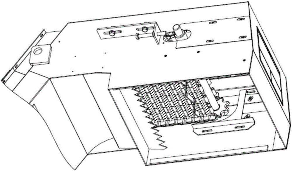
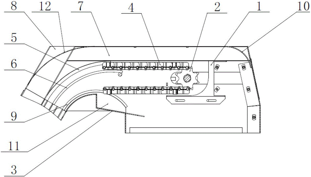
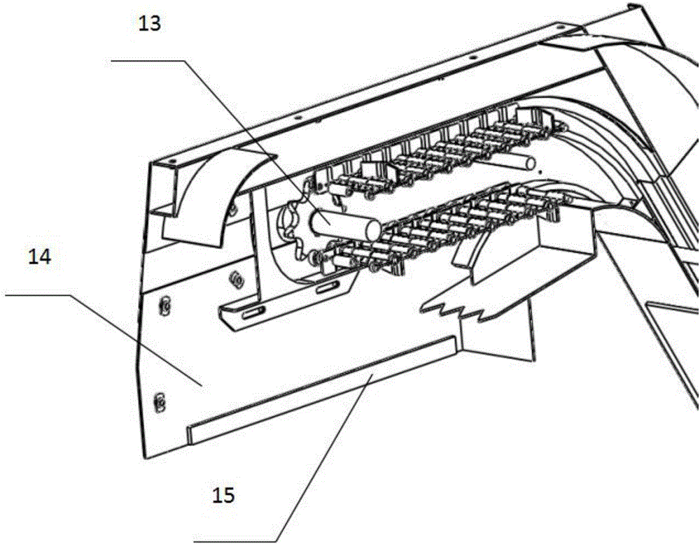
[0022] See figure 1 , figure 2 , image 3 with Figure 4 , The present invention provides a technical solution: a novel chain plate chip conveyor anti-chip structure, including a chain protection mechanism 1, a driving sprocket 2, a front axle 13, a conveying chain plate 4 and a chip outlet 15, a chain protection mechanism 1 is provided with a head arc 10, the chain protection mechanism 1 is installed on the side plate 14 of the machine head, a chip outlet 15 is provided under the side plate 14 of the machine head, and the front side of the chain protection mechanism 1 is provided with an active sprocket 2. The front axle 13 is arranged in the middle of the driving sprocket 2, and the upper and lower sides of the driving sprocket 2 are provided with conveying chain plates 4, and the left side of the conveying chain plate 4 is respectively provided with welding rails 5 and welding rails from top to bottom. In the middle 6 and the lower part of the welding track 9, a serrated sheet metal 3 is installed on the lower left of the conveyor chain plate 4, a chip guard 11 is arranged above the serrated sheet metal 3, and the left side of the machine head side plate 14 is connected with a side guard 7 and the side protection lower 8, the left end of the side plate 14 of the machine head is provided with a side arc 12; the conveyor chain 4 is composed of chain balls 41, chain scrapers 42, chain connecting pins 43, chain connecting pieces 44 and The link plate side plate 45 is constituted.
[0023] There are a plurality of link plate connecting pins 43 and link plate connecting pieces 44, a plurality of link plate connecting pins 43 and link plate connecting pieces 44 constitute a base plate, and the chain ball 41, the chain plate scraper 42 and the chain plate side plate 45 are all provided There are two, the two chain balls 41, the chain scraper 42, and the chain side plate 45 are symmetrically arranged on the base plate.
[0024] Two conveying chain plates 4 are provided. The two conveying chain plates 4 have the same structure. The two conveying chain plates 4 are symmetrically installed on the upper and lower sides of the driving sprocket 2.
[0025] The saw-tooth sheet metal 3 is a saw-tooth-shaped chip guide sheet metal, which prevents long curled chips from being caught in the conveyor chain 4 again.
[0026] The head arc 10 and the side arc 12 are a kind of arc-shaped chip guide sheet metal, which is used to create a cavity to ensure that the long rolled chips are discharged from the chip outlet 15 due to the extrusion effect during operation.
[0027] The chain protection mechanism 1 is used to ensure that the running track of the conveying chain plate 4 is a straight line, and there is no left-right deviation.
[0028] The upper 5 of the welding track, the middle 6 of the welding track, the lower 9 of the welding track, the head arc 10 and the side arc 12 are used to ensure the running track of the conveyor chain 4.
[0029] As an embodiment of the present invention: the motor drives the driving sprocket 2 to rotate through a chain drive, and the driving sprocket 2 drives the conveyor chain 4 to run during the rotation. The conveyor chain 4 is running with chips, and the chain ball 41 is The welding rail and the center of the welding rail move in accordance with the running trajectory. The long group of debris is concentrated between the two adjacent chain scrapers 42 and moves to the side protection. The long group of debris is affected by the side arc 12 , The squeezing force between the side protection upper 7, the side protection lower 8, the head arc 10 and the conveying chain plate 4, ensures that the long clumps of chips are evenly transported to the chip outlet 15 of the machine head.
[0030] The chain protection mechanism 1 protects the conveyor chain plate 4 from abrasion during operation, and guarantees the running track of the conveyor chain plate 4 on the welding rail, in the welding rail and under the welding rail. The head arc 10 and side arc 12, arc transition It prevents long chips from jamming at the corners and blocking chips from causing poor operation. The conveyor chain plate 4 has its own chain plate side plate 45 structure to prevent debris from falling into the guide rail and causing debris jamming. The chip guard 11 is placed under the welding guide rail and between the sawtooth sheet metal 3 to ensure that the long group of chips runs evenly in the running track space without stagnation, resulting in chip jamming and chip blocking.
[0031] The ordinary chain plate chip conveyor has a wide application in the field of machine tool chip removal, but it cannot solve the problem of chip jamming and chip blocking in the process of long coiling and chip removal during rough machining. The present invention can solve such problems and has a simple and compact structure. , To ensure the smooth and efficient working process of the chain chip conveyor, improve work efficiency, accurately simulate the running track, eliminate faults, ensure the smooth transportation of chips, increase the average running time of the chain chip conveyor, and ensure the processing efficiency of the machine tool.
[0032] The above shows and describes the basic principles and main features of the present invention and the advantages of the present invention. For those skilled in the art, it is obvious that the present invention is not limited to the details of the above exemplary embodiments, and does not deviate from the spirit or basics of the present invention. In the case of features, the present invention can be implemented in other specific forms. Therefore, from any point of view, the embodiments should be regarded as exemplary and non-limiting. The scope of the present invention is defined by the appended claims rather than the foregoing description, and therefore it is intended to fall within the claims. All changes within the meaning and scope of equivalent elements of are included in the present invention. Any reference signs in the claims should not be regarded as limiting the claims involved.
[0033] In addition, it should be understood that although this specification is described in accordance with the implementation manners, not each implementation manner only includes an independent technical solution. This narration in the specification is only for clarity, and those skilled in the art should consider the specification as a whole The technical solutions in the embodiments can also be appropriately combined to form other implementations that can be understood by those skilled in the art.

PUM

no PUM

Description & Claims & Application Information

We can also present the details of the Description, Claims and Application information to help users get a comprehensive understanding of the technical details of the patent, such as background art, summary of invention, brief description of drawings, description of embodiments, and other original content. On the other hand, users can also determine the specific scope of protection of the technology through the list of claims; as well as understand the changes in the life cycle of the technology with the presentation of the patent timeline. Login to view more.

Similar technology patents

Classification and recommendation of technical efficacy words

  • Simple and compact structure
  • Improve work efficiency

Opening-nozzle saddle-shaped seam welding equipment

Owner:BEIJING INSTITUTE OF PETROCHEMICAL TECHNOLOGY

Improved novel energy automobile charging device

Owner:XIAMEN YINLV JIEYUAN ENVIRONMENTAL PROTECTION TECH CO LTD

Full-automatic water-drill grinding and polishing machine

InactiveCN101758433AImprove work efficiencyFixture positioning is accurateEdge grinding machinesManipulatorEngineering
Owner:瑞安市天成包装机械有限公司
Why Eureka
Try Eureka