Bidirectionally-transformable unmanned aerial vehicle of H-shaped structure

A technology of unmanned aerial vehicles and lifting structures, applied in the field of unmanned aerial vehicles, can solve problems such as easy shooting of the machine arm, loss of stability, and affecting shooting effects, etc., to achieve the effects of improving shooting effects, improving use conditions, and improving practicability

Inactive Publication Date: 2016-12-07
SICHUAN COLLEGE OF ARCHITECTURAL TECH
View PDF9 Cites 6 Cited by
  • Summary
  • Abstract
  • Description
  • Claims
  • Application Information

AI Technical Summary

Problems solved by technology

[0003] The structure of the existing UAV is relatively simple, and the arm and the body are both fixed structures. During the flight, the UAV is easily affected by the external environment and loses stability. Some UAVs that perform camera tasks need to install a camera , due to the inability to maintain a relatively stable flight, it is easy to shoot the arm, which greatly affects the shooting effect, greatly prolongs the operation time of the drone, and increases the mi...

Method used


Image

  • Bidirectionally-transformable unmanned aerial vehicle of H-shaped structure
  • Bidirectionally-transformable unmanned aerial vehicle of H-shaped structure
  • Bidirectionally-transformable unmanned aerial vehicle of H-shaped structure

Examples


Embodiment 1

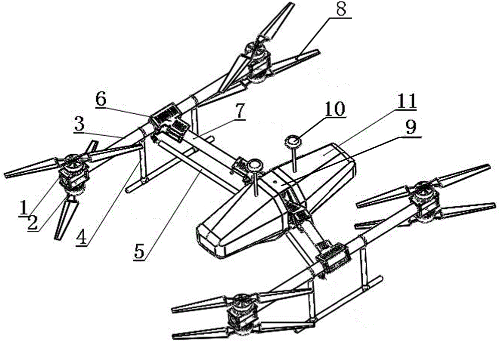
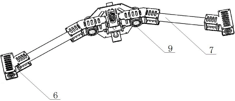
[0036] The main structure of this embodiment, such as figure 1 As shown, it includes a machine body 11 and machine arms 3 that are arranged on both sides of the machine body 11 and are parallel to each other. The middle part of the machine body 11 is provided with a lifting structure 9, and the lifting structure 9 is fixed on the middle part of the machine arm 3 through a transverse force tube 7. The oblique T-shaped piece 6 is connected, and the two ends of the arm 3 are provided with rotor assemblies.

[0037] The specific implementation is that during the flight of the UAV, the lifting structure 9 in the middle of the body 11 can be used to make the arm 3 rise or fall under the action of the transverse force tube 7, as Figure 4 , Figure 5 , Image 6 , Figure 7 As shown, the rise or fall of the drone arm 3 can better adjust the center of the drone, so that the drone can adapt to a variety of complex high-altitude environments and improve the stability of the drone; at ...

Embodiment 2

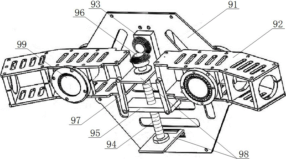
[0040] On the basis of the above-mentioned embodiments, this embodiment further defines the specific structure of the lifting structure 9, such as figure 2 As shown, the lifting structure 9 includes a fixed plate 91, the middle part of the fixed plate 91 is provided with a drive motor, and a lead screw 94 connected with the drive motor, and the two sides of the lead screw 94 are respectively provided with a rotating shaft 99 fixed on the The connector 92 on the fixed plate 91, one end of the connector 92 is connected with the transverse stress tube 7; The draw bar 97 that part 92 free ends are connected.

[0041] The machine arm of unmanned aerial vehicle is when lifting, and is rotated by drive motor drive lead screw 94, and lead screw 94 provides rotational force for lift plate 95, because lead screw 94 is fixed on the fixed plate 91, so the lift plate 95 in the middle of lead screw 94 Do lifting motion on leading screw 94. Since the lifting plate 95 is connected by the fre...

Embodiment 3

[0043] On the basis of the above-mentioned embodiments, this embodiment further defines the connection relationship between the drive motor and the lead screw 94, such as figure 2 As shown, the driving motor is provided with a driving bevel gear 93, and the top of the screw 94 is provided with a driven bevel gear 96, the axis of the driving bevel gear 93 is perpendicular to the axis of the driven bevel gear 96, and the driving bevel gear The gear 93 meshes with a driven bevel gear 96 . The driving motor drives the leading screw 94 to rotate by driving the bevel gear 93 and the driven bevel gear 96, and the driving bevel gear 93 axis is perpendicular to the driven bevel gear 96 axis, so that the drive motor and the leading screw 94 The installation position is more flexible, and the lifting of the drone arm 3 is better realized. Other parts of this embodiment are the same as those of the foregoing embodiment, and will not be repeated here.


PUM


Abstract

The invention discloses a bidirectionally-transformable unmanned aerial vehicle of an H-shaped structure. The bidirectionally-transformable unmanned aerial vehicle of the H-shaped structure comprises a fuselage and arms which are arranged on the two sides of the fuselage and are parallel to each other. A lifting structure is arranged in the middle of the fuselage. The lifting structure is connected with oblique T-shaped parts through transverse stress pipes, and the oblique T-shaped parts are fixed to the middle portions of the arms correspondingly. Rotor wing assemblies are arranged at the two ends of each arm correspondingly. According to the bidirectionally-transformable unmanned aerial vehicle of the H-shaped structure, the lifting structure is additionally arranged on the fuselage so that the arms of the unmanned aerial vehicle can rise and fall, the center of the unmanned aerial vehicle can be better adjusted, the unmanned aerial vehicle can adapt to various complex high-altitude environment, and the stability of the unmanned aerial vehicle is improved; the unmanned aerial vehicle can be protected against disturbance from the arms when executing shooting work, and the shooting effect of the unmanned aerial vehicle is improved; and folding of the fuselage and the arms of the unmanned aerial vehicle is achieved, the arms and the fuselage of the unmanned aerial vehicle can be folded together in the unmanned aerial vehicle transporting process, the size of the unmanned aerial vehicle is reduced, the assembled and debugged unmanned aerial vehicle can be directly used conveniently when needed, and the practicability of the unmanned aerial vehicle is improved.

Description

technical field [0001] The invention relates to the technical field of unmanned aerial vehicles, in particular to an H-shaped structural bidirectionally deformable unmanned aerial vehicle frame. Background technique [0002] Unmanned aircraft, referred to as "drone" for short, and "UAV" for English abbreviation, is an unmanned aircraft controlled by radio remote control equipment and its own program control device. From a technical point of view, it can be divided into: unmanned fixed-wing aircraft, unmanned vertical take-off and landing aircraft, unmanned airship, unmanned helicopter, unmanned multi-rotor aircraft, unmanned parawing aircraft, etc. UAVs can carry a variety of loads to complete various complex tasks, and are widely used in many fields such as photography, pesticide spraying, fire prevention and disaster relief, communication, and anti-drug. [0003] The structure of the existing UAV is relatively simple, and the arm and the body are both fixed structures. Du...

Claims


Application Information

Patent Timeline
IPC IPC(8): B64C1/30B64C27/10
CPCB64C1/30B64C27/10B64U2101/30B64U10/10
Inventor 王海涛程浩
Owner SICHUAN COLLEGE OF ARCHITECTURAL TECH
Why Eureka
Try Eureka