
LED daytime driving lamp

A technology of LED lamp beads and running lights, which is applied in the directions of motor vehicles, road vehicles, cooling/heating devices of lighting devices, etc., can solve the problem of unreasonable structural design of LED light source heat dissipation plate and increase the maintenance cost of LED daytime running lights. , Affect the visual effect and safety performance of the additional driving vehicle, so as to reduce the space volume of lamps, ensure the visual effect and safety performance, and avoid the effect of functional failure.

Inactive Publication Date: 2016-12-07
南宁燎旺车灯股份有限公司
View PDF5 Cites 0 Cited by
  • Summary
  • Abstract
  • Description
  • Claims
  • Application Information

AI Technical Summary

Problems solved by technology

However, the current LED daytime running lights generally have the following problems: (1) Due to the high luminous intensity of the LED light source, it is easy to produce dazzling adverse effects, which affects the visual effect and safety performance of the driving car, and greatly reduces the safety of driving. (2) When the size of the lamp assembly space is limited, the layout of the built-in light source of the lamp is unreasonable, and the arrangement of the lamps is chaotic, which increases the space occupied by the lamps and affects the appearance of the lamps; (3) in the assembly of lamps In the case of limited space size, the structural design of the LED light source cooling plate is unreasonable, and the heat dissipation problem of the LED light source will lead to functional failures from time to time, which will reduce the service life of the daytime running lights and increase the maintenance cost of the LED daytime running lights

Method used


Image

  • LED daytime driving lamp
  • LED daytime driving lamp
  • LED daytime driving lamp

Examples


Embodiment Construction

[0016] The present invention will be further described below in conjunction with accompanying drawing:

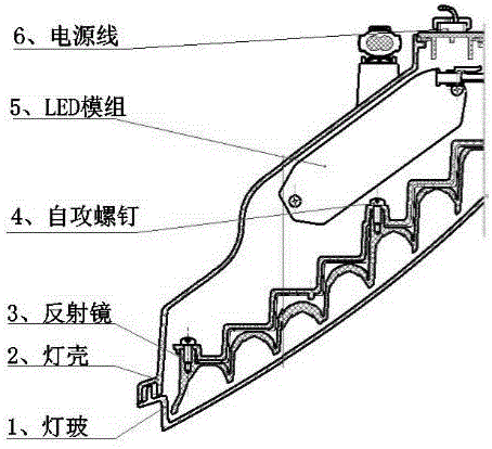
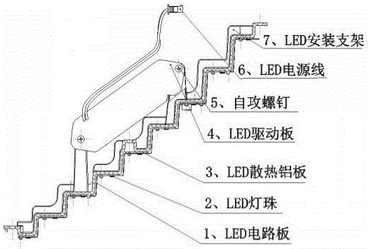
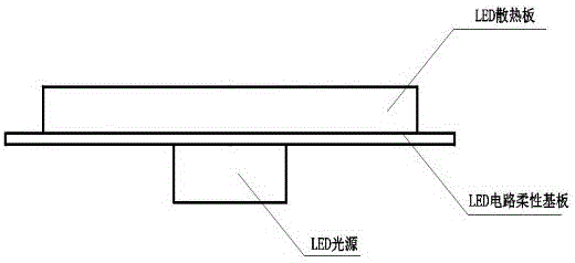
[0017] figure 1 Shown is a structural schematic diagram of the LED daytime running lamp of the present invention, as figure 1 , an LED daytime running light, mainly sealed by a lamp glass (1), a lamp housing (2), a reflector (3), self-tapping screws (4), an LED module (5), and a power cord (6) Assembly composition, characterized in that: the reflector (3) is connected to the lamp glass (1) through self-tapping screws (4), the shape of the reflector (3) is 60°-90° zigzag, the The LED module (5) is composed of LED circuit board 1, LED lamp bead 2, LED heat dissipation aluminum plate 3, LED driver board 4, self-tapping screw 5, LED power cord 6, LED mounting bracket 7, and each LED lamp bead 2 is respectively It is connected with an LED heat-dissipating aluminum plate 3, and the power cord (6) and the LED power cord 6 of the LED module (5) are connected with the LED driver b...


PUM


Abstract

The invention relates to an LED daytime driving lamp. The LED daytime driving lamp is mainly formed by assembling lamp glass, a lamp housing, a mirror, self-tapping screws, an LED module and a power line in a sealed manner, and is characterized in that the mirror is connected with the lamp glass through the self-tapping screws; the mirror is in a zigzag shape with the angle ranging from 60 degrees to 90 degrees; the LED module is composed of an LED circuit board, LED lamp beads, an LED cooling aluminum plate, an LED drive board, self-tapping screws, an LED power line and an LED installation support. By means of the LED daytime driving lamp, the brightness of daytime driving lamps is improved, the requirement of the regulation ECE R87 is met, a striking vision effect is achieved for drivers, and the safety performance of driving is improved; the LED light source independent type aluminum substrate cooling structure is adopted, the service life of the LED daytime driving lamp is prolonged, and the maintenance cost is reduced; and the form design of independent type single lamps or combined lamps is adopted, lamp structures can be reasonably arranged under the condition that the size of the lamp assembling space is limited, and the lamp space size is reduced.

Description

technical field [0001] The technology of the present invention belongs to the field of automobile engineering, and in particular relates to an LED daytime running light. Background technique [0002] Daytime running lights are special lights that are automatically turned on when the car engine is started. Its function is to allow other road users to better perceive and identify when driving in daytime or in rainy and foggy weather. According to official statistics, the installation of daytime running lights on vehicles can reduce vehicle accidents by 12.4%, and also reduce the probability of death in car accidents by 26.45%. Early daytime running lights used halogen bulb light sources, which had the disadvantages of short service life and high power consumption; with the emergence of LED green light sources, most daytime running lights use LED configurations, which have long life, small size, good stability, and fast response. and other characteristics. The application of ...

Claims


Application Information

Patent Timeline
IPC IPC(8): F21S8/10F21V7/04F21V17/12F21V23/00F21V29/503F21W101/02F21Y115/10F21W107/10
CPCF21V17/12F21V23/00
Inventor 邓建国卢军李向宁樊一杭唐创新黄性刚李小军张伟江
Owner 南宁燎旺车灯股份有限公司
Learn More