Method and device for testing pressure resistance of optical fiber coating

A technology of optical fiber coating and testing method, which is applied to measuring device, using stable tension/pressure to test material strength, strength characteristics, etc. Different, easily affected by test conditions, etc., to achieve the effect of favoring stability and repeatability, improving stability and repeatability, and fewer components

Inactive Publication Date: 2016-12-07
JIANGSU HENGTONG OPTICAL FIBER TECH
View PDF10 Cites 3 Cited by
  • Summary
  • Abstract
  • Description
  • Claims
  • Application Information

AI Technical Summary

Problems solved by technology

Therefore, the thickness and selection of inner and outer coatings are very important for the later use of optical fibers. Appropriate selection of coating materials and coating thickness can ensure that when the optical fiber is subjected to a large compressive stress in a short period of time, the additional loss of the optical fiber is not obvious. Improper coating Layer material and coating thickness will cause greater additional loss when the optical fiber is subjected to compressive stress, and in severe cases, the communication system will be temporarily paralyzed
[0003] How to evaluate the influence of optical fiber coating material and coating thickness on optical fiber performance, there is no very effective method at home and abroad at present. More evaluation of optical fiber coating effect is by testing the microbending performance of optical fiber, but the test of microbending performance is easily affected The influence of test conditions, especially the repeatability of the microbending force state of the optical fiber is poor, and the results of each measurement of force are different, and international research on microbending is limited to research reports

Method used


Image

  • Method and device for testing pressure resistance of optical fiber coating
  • Method and device for testing pressure resistance of optical fiber coating
  • Method and device for testing pressure resistance of optical fiber coating

Examples


Embodiment 1

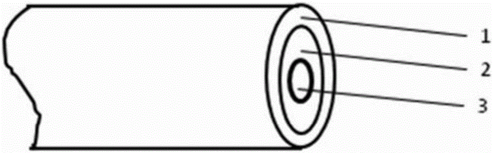
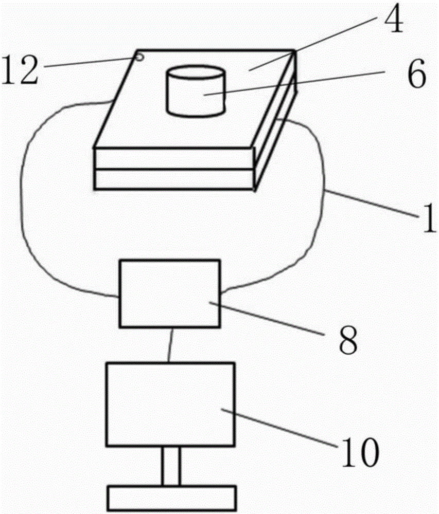
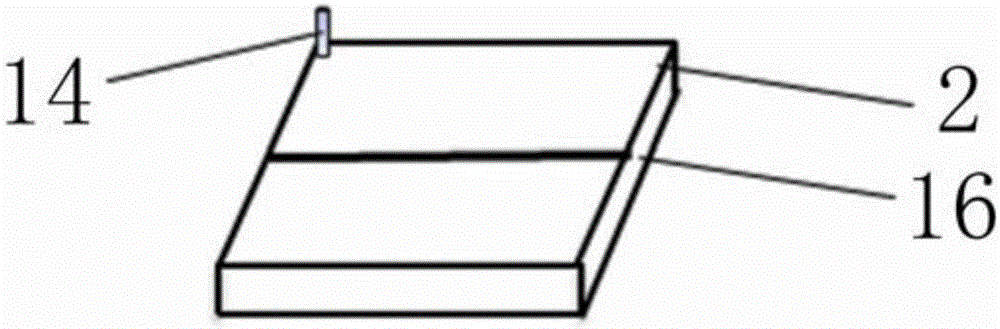
[0040] like figure 2 , 3 As shown, a device for measuring the pressure resistance performance of optical fiber coating is disclosed in this embodiment, which includes a test substrate 2, a pressure plate 4, a counterweight 6, an optical power meter 8 and a computer 10, wherein the test substrate 2 and the pressure plate 4 are all used Stainless steel plate, in the early stage, the stainless steel plate is processed into a rectangular parallelepiped structure with a length of 25-30mm, a width of 15-20mm, and a height of 20-30mm to form a test substrate 2 and a pressure plate 4, both of which are in contact with the surface of the optical fiber 1 to be tested ( That is, the surface roughness of the test surface) is 0.05-0.1um, and the test reference line 16 is made at the center of the width of the test substrate 2 to ensure that the optical fiber 1 is placed along the test reference line 16 for each test. During the measurement, the press plate 4 is fitted and arranged direct...

Embodiment 2

[0042] The present embodiment provides a test method for testing the pressure resistance performance of the optical fiber coating based on the above-mentioned measuring device, which includes the following steps:

[0043] (1) Take an optical fiber and intercept three sections of equal length, with a length of 3-5m, to form three sections of optical fiber to be tested, namely L1, L2, and L3;

[0044] (2) Under the test conditions that the temperature is 20°C-28°C and the humidity is RH40%-60%, the test substrate 2 is placed on a stable working platform, and the middle part of the optical fiber L1 to be tested in the Pass through the surface of the substrate 2, first fix a free end of the optical fiber L1 on the working platform with adhesive tape, straighten the optical fiber L1 so that the optical fiber L1 coincides with the test reference line 16 on the test substrate 2, and then tape the optical fiber L1 The other free end is fixed on the working platform. The pressure plate a...

Embodiment 3

[0051] Steps (2) to (4) of this embodiment are the same as those in Embodiment 1,

[0052] (5) Take two counterweights 6 with a weight of 50-500 g and place them on the center of the pressure plate 4, and measure the optical power loss of the optical fiber L1 after placing the two counterweights according to the method of step (4), denoted as X2;

[0053] (6) The difference between X2 and X0 is the optical power loss under the pressure of the two counterweights of the optical fiber L1, denoted as Δ1;

[0054] (7) Follow the steps (2) to (6) to test the optical power loss of the optical fiber L2 to be tested and the optical fiber L3 to be tested under the pressure of two counterweights, which are respectively recorded as Δ1, Δ2 and Δ3, and Δ1, Δ2 and Δ3 are taken the average of the three As the optical power loss of the entire fiber under test.


PUM


Abstract

The invention provides a method for testing the pressure resistance of optical fiber coating. The method includes the steps of firstly, placing a testing substrate on a work platform, allowing the middle part, in the length direction, of an optical fiber to pass the surface of the testing substrate, using tape to fix one free end of the optical fiber on the work platform, straightening the optical fiber to allow the same to coincide with a testing datum line on the testing substrate, and using tape to fix the other free end of the optical fiber on the work platform; secondly, lightly pressing a pressing plate identical with the testing substrate in specification on the testing substrate, and electrically connecting the two free ends of the optical fiber with an optical power meter; thirdly, recording the display value of the optical power meter at the moment, testing the optical power loss of the optical fiber according to a power transmission method in IEC60793-1-40, and recording the optical power loss as X0; fourthly, placing appropriate counter weight at the center of the pressing plate, testing the optical power loss of the optical fiber after the counter weight is placed according to the method in the third step, and recording the optical power loss as X1; fifthly, using the difference value between X1 and X0 as the optical power loss, under the pressure of the counter weight, of the optical fiber. By the method, testing stability and repeatability can be guaranteed.

Description

technical field [0001] The invention belongs to the technical field of optical fiber detection, and in particular relates to a method for testing the pressure resistance performance of an optical fiber coating and a measuring device thereof. Background technique [0002] like figure 1 As shown, the optical fiber is usually composed of a bare fiber 11, an inner coating 13 and an outer coating 15. The inner coating is generally soft and has a low modulus, and the outer coating is generally hard. The inner coating is used to protect the bare fiber. When the fiber is stressed, it can be released, and the outer coating can protect the fiber from the impact of external forces. Therefore, the thickness and selection of inner and outer coatings are very important for the later use of optical fibers. Appropriate selection of coating materials and coating thickness can ensure that when the optical fiber is subjected to a large compressive stress in a short period of time, the additio...

Claims


Application Information

Patent Timeline
Patent Type & Authority Applications(China)
IPC IPC(8): G01N3/08
CPCG01N3/08G01N2203/0003G01N2203/0019G01N2203/0032G01N2203/028G01N2203/0641
Inventor 贺作为陈伟朱永刚张良于海明袁健
Owner JIANGSU HENGTONG OPTICAL FIBER TECH
Why Eureka
Try Eureka