Latent heat type cooling system for underground nuclear power station containment

A nuclear power plant containment and cooling system technology, applied in the field of nuclear power, can solve the problems of cooling water consumption, low heat exchange efficiency, and low cooling efficiency, and achieve the effect of increasing heat exchange capacity, high heat exchange efficiency, and rapid heat dissipation

Active Publication Date: 2016-12-07
CHANGJIANG SURVEY PLANNING DESIGN & RES
View PDF12 Cites 3 Cited by
  • Summary
  • Abstract
  • Description
  • Claims
  • Application Information

AI Technical Summary

Problems solved by technology

However, this heat conduction method has low heat exchange efficiency, especially the problem of low efficiency when the heat in the containment is discharged to the heat exchanger.
For example, the Chinese patent: Passive containment cooling system (application number: CN201310328514.5) utilizes the evaporator installed in the pile pit to export the heat in the containment, but this cooling method only has a high cooling efficiency near the evaporator, which is safe. The shell heat must first be transferred to the vicinity of the evaporator before it can be further exported; Chinese patent: a passive containment cooling system and method (application number: CN201210088007.4) uses the condensing heat exchanger in the external condensing water tank to export the containment Heat, this conde

Method used


Image

  • Latent heat type cooling system for underground nuclear power station containment
  • Latent heat type cooling system for underground nuclear power station containment
  • Latent heat type cooling system for underground nuclear power station containment

Examples


Embodiment Construction

[0023] The present invention will be described in further detail below in conjunction with the accompanying drawings and embodiments, but these embodiments should not be construed as limiting the present invention.

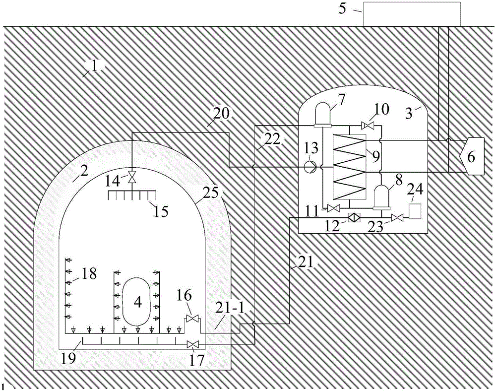
[0024] A kind of underground nuclear power plant containment latent heat type cooling system of the present invention such as figure 1 As shown, it includes a ground pool 5 on the ground, a containment vessel and a condensation cavern 3 in the underground rock formation 1 . The outer layer of the containment is the rock mass reconstruction layer 2. The upper part of the inner cavity of the containment shell 25 is provided with an air suction branch pipe 15 , and the lower part is provided with an atomizing nozzle 18 and a dry cold air distribution branch pipe 19 .

[0025] A condensation heat exchanger 9 is arranged in the condensation cavern 3, and the cooling water pipe of the condensation heat exchanger 9 is connected with the external heat sink 6 and the grou...


PUM

PropertyMeasurementUnit
Diameteraaaaaaaaaa

Abstract

The invention discloses a latent heat type cooling system for an underground nuclear power station containment. The latent heat type cooling system for the underground nuclear power station containment comprises a surface pond positioned on the ground, and a containment and a condensation cavern which are positioned in underground rock stratum, wherein a rock mass modification layer arranged on the outer layer of the containment, an inspiration branch pipe is arranged at the upper part of the inner chamber of the containment, atomizing nozzles and dry and cold air shunt pipes are arranged at the lower part of the inner chamber of the containment, the atomizing nozzles are distributed on the side wall and the bottom of a pressure vessel, and the dry and cold air shunt pipes are positioned below the atomizing nozzles; a condensation heat regenerator is arranged inside the condensation cavern, the air inlet of the condensation heat regenerator is connected with the inspiration branch pipe, and an outlet is connected with the dry and cold air shunt pipes. According to the system provided by the invention, a cooling liquid is atomized to be tiny fog droplets, so that the contact surface between the cooling liquid and air is sharply increased, the heat exchange capability is enhanced, and the latent heat of evaporation of the tiny fog droplets is used for quickly and efficiently carrying away heat inside the containment. Moreover, the condensation heat regenerator inside the condensation cavern is used for condensation of air inside the containment and heat export, and long term close type circulation cooling is achieved.

Description

technical field [0001] The invention relates to nuclear power technology, in particular to a latent heat cooling system for containment of underground nuclear power plants. Background technique [0002] Underground nuclear power plants place nuclear islands and other nuclear-related plants underground, and use the protection and containment of underground rock mass to limit the release of potential radioactive substances to the environment, improve the safety of nuclear power plants, and provide new ideas for the safe development of nuclear power in my country. [0003] In a severe accident of a nuclear power plant, the core melt is ejected from the pressure vessel, rapidly heating the atmosphere in the containment, and at the same time, due to the evaporation of the high-temperature coolant, a high-temperature, high-pressure atmospheric environment is formed in the containment. At this time, in order to prevent the failure of the integrity of the containment vessel, the hea...

Claims


Application Information

Patent Timeline
IPC IPC(8): G21C15/18
CPCG21C15/182Y02E30/30
Inventor 张涛钮新强赵鑫喻飞金乾袁博刘爽何杰李成子付文军
Owner CHANGJIANG SURVEY PLANNING DESIGN & RES
Why Eureka
Try Eureka