Fuse with internal buffer layer, and manufacturing method for fuse

A buffer layer and fuse technology, applied in the field of fuses, can solve problems such as discrete resistance of fuse links, defects of fuse links, and endangering line safety, so as to improve withstand voltage capability and safe breaking capability, and overcome shrinkage mismatch or mutual diffusion , Guarantee the effect of arc extinguishing and pressure resistance

Active Publication Date: 2016-12-07
AEM COMPONENTS
View PDF7 Cites 6 Cited by
  • Summary
  • Abstract
  • Description
  • Claims
  • Application Information

AI Technical Summary

Problems solved by technology

[0003] With the increase of the voltage in the circuit, the safety hazards such as substrate breakage, fragmentation, burning board and substrate flying off the circuit board will occur when the fuse cannot withstand the voltage increase during the fusing process. Therefore, it is necessary to improve the withstand voltage capacity of the fuse
The Chinese invention with the application number 201010122121.5 adopts the embedded circuit lamination method, at least one pressure relief and heat accumulation space is provided between two stacked substrates, and the fuse is inserted in the pressure relief and heat accumulation space. The thermal space can accumulate the high temperature generated by the fuse when the current passes through, and can release the pressure generated by the fuse when it is blown; but the disadvantage of this method is that the fuse is installed in the pressure relief and heat accumulation space, at least One side is in the groove and the patent mentions that the protective element will be sintered, and the sintering process is the shrinkage and densification process of the fuse link and the ceramic substrate. Since at least one side of the fuse link is in the groove structure, it cannot shrink together with the substrate. It is easy to cause bending deformation of the fuse link, and at the same time, due to gravity, the fuse link will also bend and deform towards the groove surface. The bending deformation of the fuse link will lead to poor consistency of the fuse, and it is prone to nonlinear fusing Affect the normal operation of the line
[0004] The Chinese invention with the application number 201210277104.8 adopts a stamping groove on the ceramic substrate of the component, and the porous ceramic slurry or pore-forming agent slurry of LTCC is filled in the stamping groove, and the porous ceramic slurry or pore-forming agent slurry filled with LTCC The melt layer is stacked on the ceramic substrate of the porogen slurry so that the melt is located directly above the punched groove of the porous ceramic slurry or porogen slurry filled with L

Method used


Image

  • Fuse with internal buffer layer, and manufacturing method for fuse
  • Fuse with internal buffer layer, and manufacturing method for fuse
  • Fuse with internal buffer layer, and manufacturing method for fuse

Examples


Embodiment 1

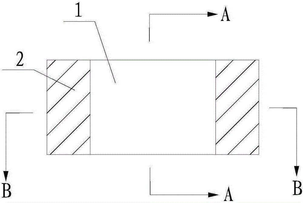
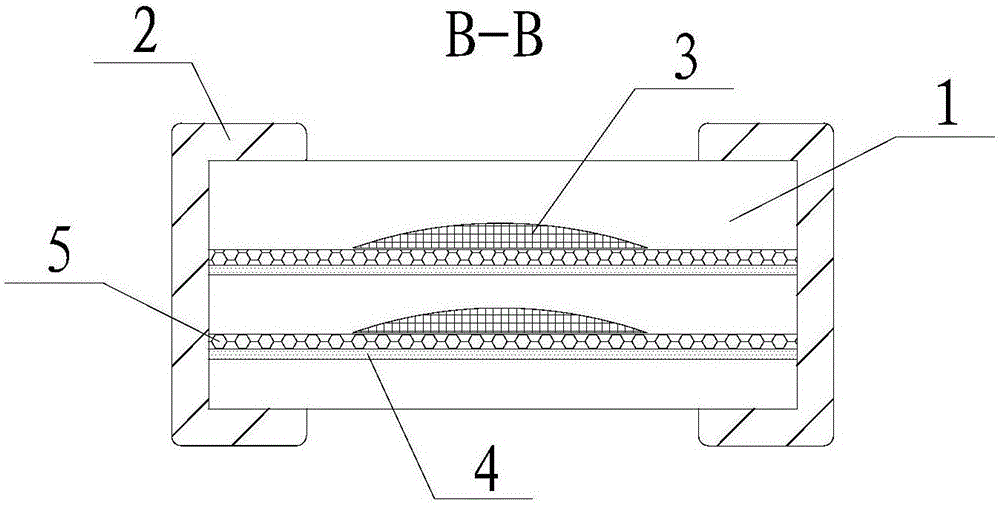
[0042] like Figure 1 to Figure 4 The shown fuse with a built-in buffer layer mainly includes an insulating base 1 , a terminal electrode 2 , a buffer layer 3 , a fuse 4 and an arc extinguishing layer 5 .

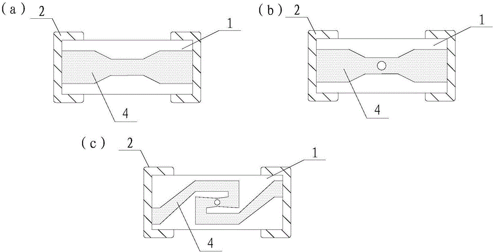
[0043] The fuse 4 is formed in the insulating matrix 1, and there is at least one in number; it can be set to a thickness corresponding to the specification according to actual needs; its shape can be straight or curved, and its fusing position is guaranteed to be in the buffer layer 3 And the area covered by the arc extinguishing layer 5 to achieve the effect of pressure relief and arc extinguishing. The fusing position can be in the shape of narrowing, prefabricated holes or grooves, as long as it can ensure that the fuse 4 can be effectively fused under the condition of high voltage and overcurrent; image 3 The fuse 4 shown in (a) has a shape of "big at both ends and small in the middle", that is, the middle of the fuse 4 is narrowed so that the width of both ends is gre...

Embodiment 2

[0055] This embodiment provides a fuse with a built-in buffer layer. Its structure is similar to that in Embodiment 1. There are two fuses 40 and two arc-extinguishing layers 50. The difference is that the buffer layer 30 and the fuse 40, The positional relationship between the arc extinguishing layers 50 is different. like Figure 5 As shown, one of the two buffer layers 30 is formed on the upper surface of the arc extinguishing layer 50 (the upper one of the two arc extinguishing layers 50), while the other is formed on the lower surface of the other fuse 40 ( the lower one of the two fuse links 40).

Embodiment 3

[0057] This embodiment provides a fuse with a built-in buffer layer. Its structure is similar to that in Embodiment 1. There are two fuses 41 and two arc-extinguishing layers 51. The difference is that there is only one buffer layer 31, such as Image 6 As shown, it is located on the upper surface of the arc extinguishing layer 51 (the upper one of the two arc extinguishing layers 51).


PUM


Abstract

The invention relates to a fuse with an internal buffer layer, and a manufacturing method for the fuse. The fuse comprises an insulating substrate, at least one fusing body formed on the insulating substrate, and end electrodes which are formed at the two ends of the insulating substrate and are connected with the fusing body; the fuse also comprises at least one arc-extinguishing layer which is formed in the insulating substrate and positioned around the fusing body, and at least one buffer layer which is formed on the peripheral surface of the arc-extinguishing layer or/and the peripheral surface of the fusing body; and the buffer layer is an accommodating space or has a porous structure. By adoption of the fuse with the internal buffer layer, problems of shrinkage mismatch or mutual diffusion of the fusing body and the buffer layer in a glue-discharging and sintering process can be overcome; phenomena of deformation, bending, defects and the like of the fusing body can be avoided; concentrated resistance value distribution and high fusing linearity of the fusing body are ensured, and a fusing non-linear phenomenon is avoided; and meanwhile, the normal operation of a circuit can be ensured.

Description

technical field [0001] The invention belongs to the field of fuses and relates to a fuse, in particular to a fuse with a built-in buffer layer and a manufacturing method thereof. Background technique [0002] With the development of science and technology, electric / electronic products are increasingly diversified and complex, and the circuit protection components used are no longer simple glass tube fuses in the past, but have developed into a wide variety of new electronic components. As a new type of thin, light and small component, the fuse is suitable for the protection circuit of various electronic products with compact structure and small size, and its application field is very wide. [0003] With the increase of the voltage in the circuit, the safety hazards such as substrate breakage, fragmentation, burning board and substrate flying off the circuit board will occur when the fuse cannot withstand the voltage increase during the fusing process. Therefore, it is necess...

Claims


Application Information

Patent Timeline
IPC IPC(8): H01H85/00H01H85/06H01H85/38
CPCH01H85/0039H01H85/06H01H85/38H01H2085/388
Inventor 林丹博杨永林徐恩慧李向明汪立无陈锡庆
Owner AEM COMPONENTS
Why Eureka
Try Eureka