Graphite boat assembling and disassembling machine capable of preventing internal silicon wafer from being damaged and counting graphite boat

A technology for graphite boats and silicon wafers, applied in the field of graphite boat loading and unloading machines, can solve the problems of uncalculated graphite boat loading and unloading quantity, uneven force on silicon wafers, complicated technology, etc., to achieve convenient statistics of work quantity, safe and convenient use, Scientific and reasonable structure

Inactive Publication Date: 2016-12-07
WENZHOU JULIANG PHOTOVOLTAIC TECH CO LTD
View PDF3 Cites 1 Cited by
  • Summary
  • Abstract
  • Description
  • Claims
  • Application Information

AI Technical Summary

Problems solved by technology

[0004] The purpose of the present invention is to provide a graphite boat loading and unloading machine that prevents internal silicon chips from being damaged and counts graphite boats, so as to solve the problem that the existing graphite boat loading and unloading machines proposed in the above-mentioned background technology are in contact with the suction cup on the silicon wafer and the mechanical arm. It is easy to cause deformation and distortion caused by uneven force on the silicon wafer, and the loading and unloading quantity of the graphite boat is not calculated. Again, the technology is complicated and time-consuming

Method used


Image

  • Graphite boat assembling and disassembling machine capable of preventing internal silicon wafer from being damaged and counting graphite boat
  • Graphite boat assembling and disassembling machine capable of preventing internal silicon wafer from being damaged and counting graphite boat

Examples


Embodiment Construction

[0014] The following will clearly and completely describe the technical solutions in the embodiments of the present invention with reference to the accompanying drawings in the embodiments of the present invention. Obviously, the described embodiments are only some, not all, embodiments of the present invention. Based on the embodiments of the present invention, all other embodiments obtained by persons of ordinary skill in the art without making creative efforts belong to the protection scope of the present invention.

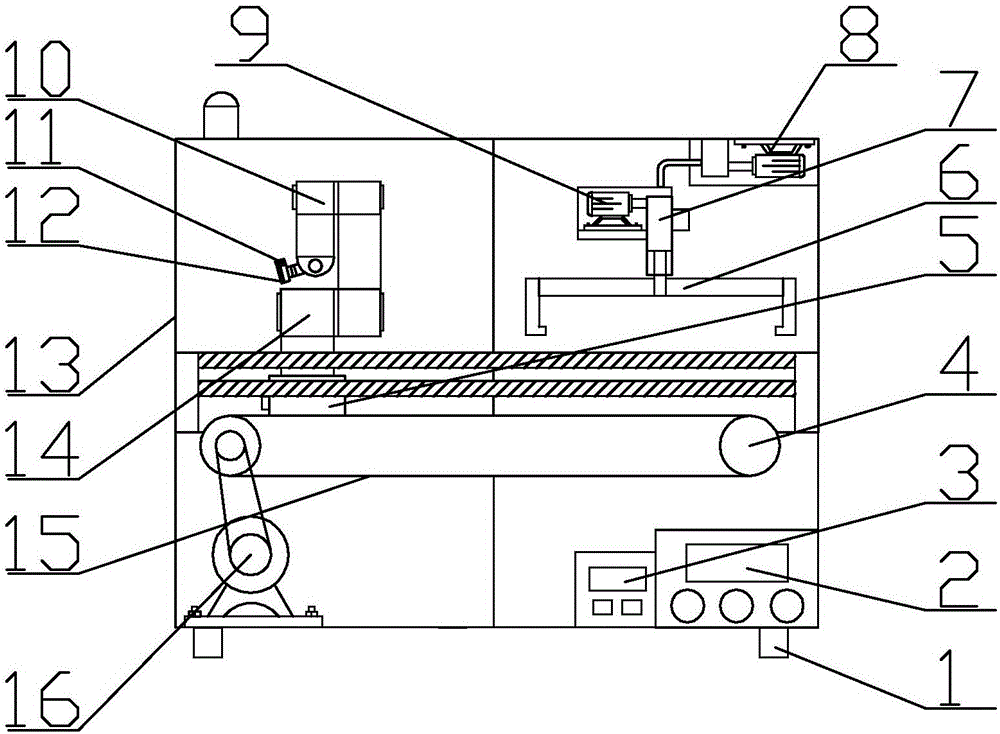
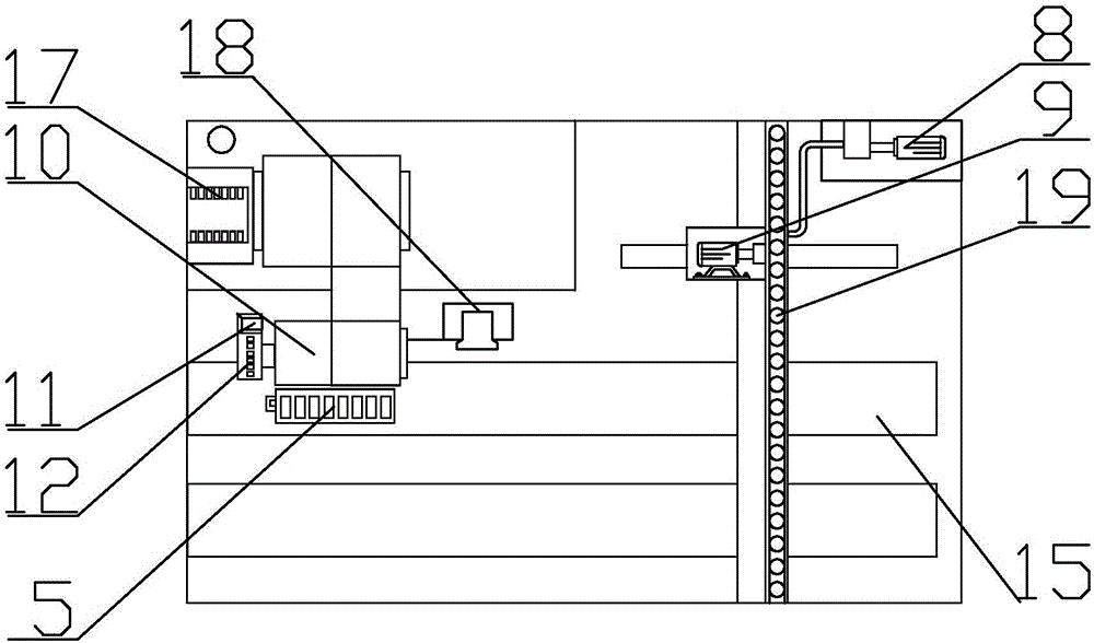
[0015] see figure 1 and figure 2 , the present invention provides a technical solution: a graphite boat loading and unloading machine for preventing internal silicon chips from being damaged and counting graphite boats, including an infrared emitter 11, a mechanical sucker 12 and a loading and unloading machine shell 13, and a loading and unloading machine shell The bottom of 13 is provided with a base pillar 1, and the front surface lower right of the loadi...


PUM


Abstract

The invention discloses a graphite boat assembling and disassembling machine capable of preventing an internal silicon wafer from being damaged and counting a graphite boat. The graphite boat assembling and disassembling machine comprises an infrared emitter, a mechanical suction disc and an assembling and disassembling machine shell, wherein a base strut is arranged below the assembling and disassembling machine shell, a control panel is arranged at a position above a part, near to the base strut, of a right lower part of a front surface of the assembling and disassembling machine shell, a time controller is arranged at a left side of the control panel, and a rotation motor is arranged at a left side, near to the time controller, of a left lower part of the interior of the assembling and disassembling machine shell. The graphite boat assembling and disassembling machine is scientific and reasonable in structure and is safe and convenient to use; compared with a traditional graphite boat assembling and disassembling machine, the graphite boat assembling and disassembling machine has the advantages of high efficiency and rapidness; a counter sensor is arranged aside a conveying belt and is used for counting the graphite boats, and the statistic work quantity is facilitated; and meanwhile, the infrared emitter is arranged aside the mechanical suction disc, and the problem of damage to the silicon wafer due to an inclined position of the suction disc is prevented when an infrared receiver on the graphite boat receives an infrared ray to work.

Description

technical field [0001] The invention belongs to the technical field of graphite boat loading and unloading machines, in particular to a graphite boat loading and unloading machine which prevents internal silicon chips from being damaged and counts graphite boats. Background technique [0002] In order to reduce light reflection, increase surface passivation, and improve the conversion efficiency of solar cells, solar cell silicon wafers need to be precisely mounted on the electrodes of graphite boats for plasma chemical vapor deposition. The loading and unloading process of solar cell silicon wafers on graphite boat electrodes adopts automatic processing, which can reduce labor intensity of workers, reduce particle pollution, improve product quality and improve the automation level of solar cell production lines. [0003] The existing graphite boat loading and unloading machine is easy to cause deformation and distortion of the silicon wafer due to uneven force when the sili...

Claims


Application Information

Patent Timeline
IPC IPC(8): H01L31/18H01L21/677
CPCH01L21/67763H01L21/67781H01L31/1876Y02P70/50
Inventor 蔡伦
Owner WENZHOU JULIANG PHOTOVOLTAIC TECH CO LTD
Why Eureka
Try Eureka