Magnetism increasing type internal tangential adjustable flux motor

A magnetic flux motor and magnetic technology, applied in the direction of magnetic circuit shape/style/structure, magnetic circuit, electric components, etc., can solve the problems of uncontrollable demagnetization of alnico permanent magnets, etc., to ensure stability, controllability, change Air-gap flux, possibility reduction effect

Inactive Publication Date: 2016-12-07
HARBIN INST OF TECH
View PDF3 Cites 15 Cited by
  • Summary
  • Abstract
  • Description
  • Claims
  • Application Information

AI Technical Summary

Problems solved by technology

[0003] The purpose of the present invention is to solve the problem of uncontrollable demagnetization of AlNiCo permanent magnets prone to occur in high-load operation of a field-weakening adjustable flux motor, and at the same time reduce the difficulty of accurately adjusting the magnetization of AlNiCo permanent magnets online, and provide a This type uses AlNiCo permanent magnets and NdFeB permanent magnets at the same time, built-in tangential magnetic poles, and the quadrature axis reactance Lq is smaller than the direct axis reactance Ld, that is, the magnetization adjustable flux motor

Method used


Image

  • Magnetism increasing type internal tangential adjustable flux motor
  • Magnetism increasing type internal tangential adjustable flux motor
  • Magnetism increasing type internal tangential adjustable flux motor

Examples


specific Embodiment approach 1

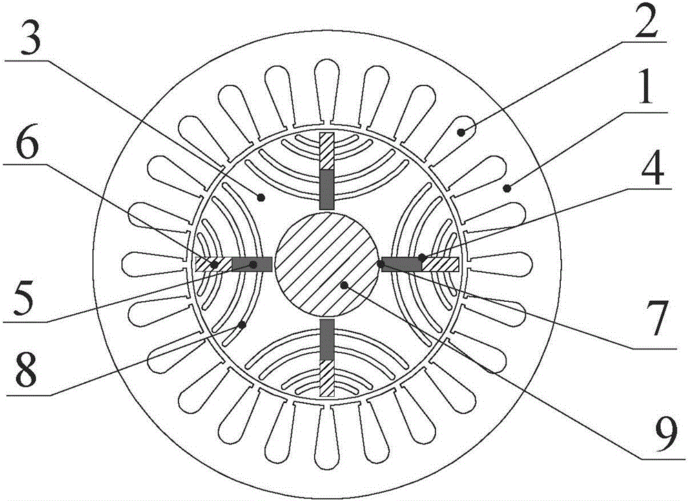
[0019] Specific implementation mode one: the following combination Figure 1 to Figure 3 Describe this embodiment, the magnetization type built-in tangentially adjustable flux motor described in this embodiment includes a stator core 1, an armature winding 2, a rotor core 3 and a rotating shaft 9; the rotor core 3 is fixed on the rotating shaft 9 and is located in the stator Inside the core 1, the armature winding 2 is arranged on the stator core 1;

[0020] It also includes tangential permanent magnet slots 4, p NdFeB magnetic poles 5, p AlNiCo magnetic poles 6 and p cross-axis magnetic barriers 8, p is an even number, and p tangential barriers are evenly arranged on the rotor core 3 along the circumference of the motor. permanent magnet slot 4 and p quadrature-axis magnetic barriers 8, and each quadrature-axis magnetic barrier 8 is a mirror-symmetrical structure centered on a tangential permanent magnet slot 4; the tangential permanent magnet slot 4 and the quadrature-axis m...

Embodiment 1

[0024] combine figure 1 To illustrate this embodiment, the magnetized built-in tangentially adjustable flux motor includes a stator, a rotor, and a rotating shaft. The stator in the present invention includes a stator core 1 and an armature winding 2. The armature winding 2 is arranged in the slot of the stator iron core, and the rotating shaft 9 is made of cast steel, and the stator and shaft 9 are the same as those of conventional permanent magnet synchronous motors; the rotor includes tangential permanent magnet slots 4, NdFeB magnetic poles 5, AlNiCo magnetic poles 6, magnetic bridges 7 and quadrature-axis magnetic barriers 8 , the tangential permanent magnet slots 4 and the quadrature-axis magnetic barriers 8 are alternately and evenly arranged on the rotor along the circumferential direction, and the tangential permanent magnet slots 4 and the quadrature-axis magnetic barriers 8 both run through the entire motor in the axial direction, and each tangential permanent magnet...

Embodiment 2

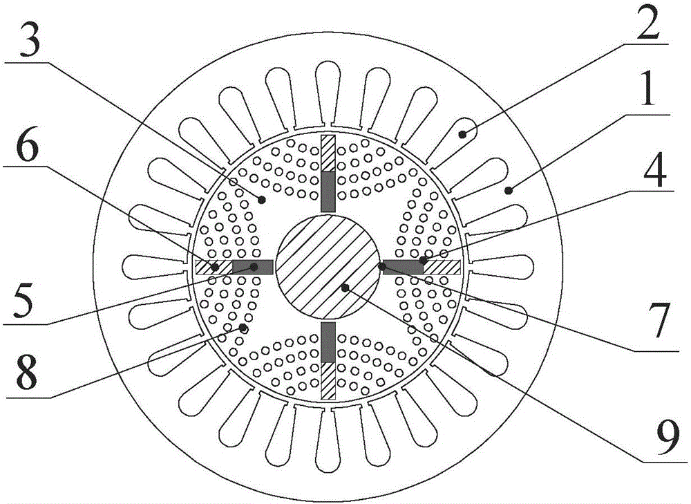
[0026] combine figure 2 Note that the difference between this embodiment and Embodiment 1 is that the quadrature-axis magnetic barrier 8 is a series of radially arranged circular groove arrays, the array is formed by multiple arc structures, and each arc structure is provided with Multiple circular slots, the number of circular slots in each circular arc structure gradually increases from outside to inside along the rotor radius direction, multiple circular arc structures take the tangential permanent magnet slot 4 as the line of symmetry, and are symmetrically arranged on the tangential permanent magnet slot 4. On both sides of the magnet slot 4, the number of circular slots can be flexibly designed on the basis of taking into account the mechanical strength of the rotor and reducing the magnetic flux path of the quadrature axis of the motor. The inside of the circular magnetic barrier can also be made of epoxy resin, carbon fiber, etc. Non-conductive material fill.


PUM


Abstract

The invention discloses a magnetism increasing type internal tangential adjustable flux motor, belongs to the field of permanent magnet motors and solves a problem that uncontrollable demagnetization of an aluminum nickel cobalt permanent magnet is easy to occur when a flux weakening type adjustable flux motor runs at high load. The magnetism increasing type internal tangential adjustable flux motor comprises a stator core, an armature winding, a rotor core, a rotating shaft, tangential permanent magnet slots, p neodymium iron boron magnetic poles, p aluminum nickel cobalt magnetic poles and p quadrature axis magnetism barriers, wherein p is an even number; the p tangential permanent magnet slots and the p quadrature axis magnetism barriers are uniformly arranged on the rotor core along the circumferential direction of the motor, and each quadrature axis magnetism barrier is of a mirror symmetry structure centering on one tangential permanent magnet slot; the tangential permanent magnet slots and the quadrature axis magnetism barriers axially penetrate through the whole rotor core; one neodymium iron boron magnetic pole and one aluminum nickel cobalt magnetic pole are both arranged in each tangential permanent magnet slot; each neodymium iron boron magnetic pole is arranged in a position close to the inner circle of a rotor in the tangential permanent magnet slot; and each aluminum nickel cobalt magnetic pole is arranged in a position close to the outer circle of a rotor in the tangential permanent magnet slot.

Description

technical field [0001] The invention belongs to the field of permanent magnet motors. Background technique [0002] In order to overcome the problems that the direct axis component of the armature current increases, the quadrature axis component decreases, the copper loss increases, and the electromagnetic torque of the motor decreases rapidly when the traditional rare earth permanent magnet motor is running at a weak field speed. The adjustable magnetic flux memory motor with coercive force AlNiCo permanent magnet came into being. When the motor is running, the air gap flux density of the permanent magnet motor is adjusted by applying the direct axis charge and demagnetization pulse current, thereby expanding the speed regulation range of the motor. . However, the quadrature-axis reactance Lq of this type of motor is often greater than the direct-axis reactance Ld during design. When the motor is running at high load, it needs a negative direct-axis current component to ge...

Claims


Application Information

Patent Timeline
Patent Type & Authority Applications(China)
IPC IPC(8): H02K1/22H02K1/27H02K1/16
CPCH02K1/22H02K1/16H02K1/2773
Inventor 郑萍张书宽佟诚德刘家琦赵白鸽
Owner HARBIN INST OF TECH
Why Eureka
Try Eureka