A kind of advanced follow-up bias method and amplifier of class A audio power amplifier

An audio power and amplifier technology, applied in the field of class A audio power amplifier, can solve the problems of rough improvement, insignificant improvement of efficiency, limited improvement, etc., to overcome the distortion problem, the best sense of hearing, and the effect of good linearity

Active Publication Date: 2017-06-30
叶鼎
View PDF3 Cites 0 Cited by
  • Summary
  • Abstract
  • Description
  • Claims
  • Application Information

AI Technical Summary

Problems solved by technology

There are common forms such as sliding bias, dynamic bias, real-time bias, continuous high bias, or super class A. These forms are unique, but there are generally problems of rough improvement and limited improvement, especially in establishing these biases and adjusting voltages. Or the current takes more time, obviously lags behind the input signal, produces more distortion, loses the good sound quality and sense of hearing of a true Class A audio power amplifier, and some are the size of the bias and the duration of the bias The time is not suitable, and the efficiency improvement is not obvious

Method used


Image

  • A kind of advanced follow-up bias method and amplifier of class A audio power amplifier
  • A kind of advanced follow-up bias method and amplifier of class A audio power amplifier
  • A kind of advanced follow-up bias method and amplifier of class A audio power amplifier

Examples


Embodiment 1

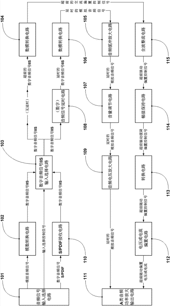
[0042] see figure 1 , a class A audio power amplifier, adopting the advanced follow-up bias method of the present invention, which includes: an audio signal input selection circuit 101, a digital-to-analog conversion circuit 102, an S / PDIF receiving circuit 110, and an IIS input selection circuit 103 , audio signal delay circuit 108, bias control signal digital-to-analog conversion circuit 104, audio signal digital-to-analog conversion circuit 106, audio buffer / amplification circuit 105, digital volume adjustment circuit 107, audio voltage amplification circuit 109, full-wave rectification circuit 115 , Amplitude hold circuit 114, conversion circuit 113, voltage or current bias circuit 112, class A audio frequency power amplification output circuit 111; Other formations of class A audio frequency power amplifier irrelevant to the present invention, for example: power supply circuit, display circuit , control circuit, sound effect processing, protection circuit, etc., will not...

Embodiment 2

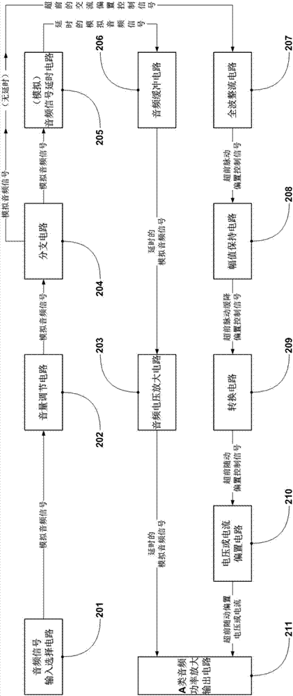
[0065] see figure 2 , a class A audio power amplifier, adopting the advanced follow-up bias method of the present invention, which includes: analog audio signal input selection circuit 201, volume adjustment circuit 202, branch circuit 204, analog signal delay circuit 205, audio Buffer circuit 206, audio voltage amplifying circuit 203, full-wave rectification circuit 207, amplitude holding circuit 208, conversion circuit 209, voltage or current bias circuit 210, A class audio frequency power amplification output circuit 211; A class irrelevant to the present invention Other necessary components of the audio power amplifier, such as power supply circuit, display circuit, control circuit, sound effect processing, protection circuit, etc., will not be described here.

[0066] The functions or effects of each part of the circuit are as follows:

[0067] Audio signal input selection circuit 201, for selecting the audio signal to be listened to;

[0068] The volume adjustment cir...

Embodiment 3

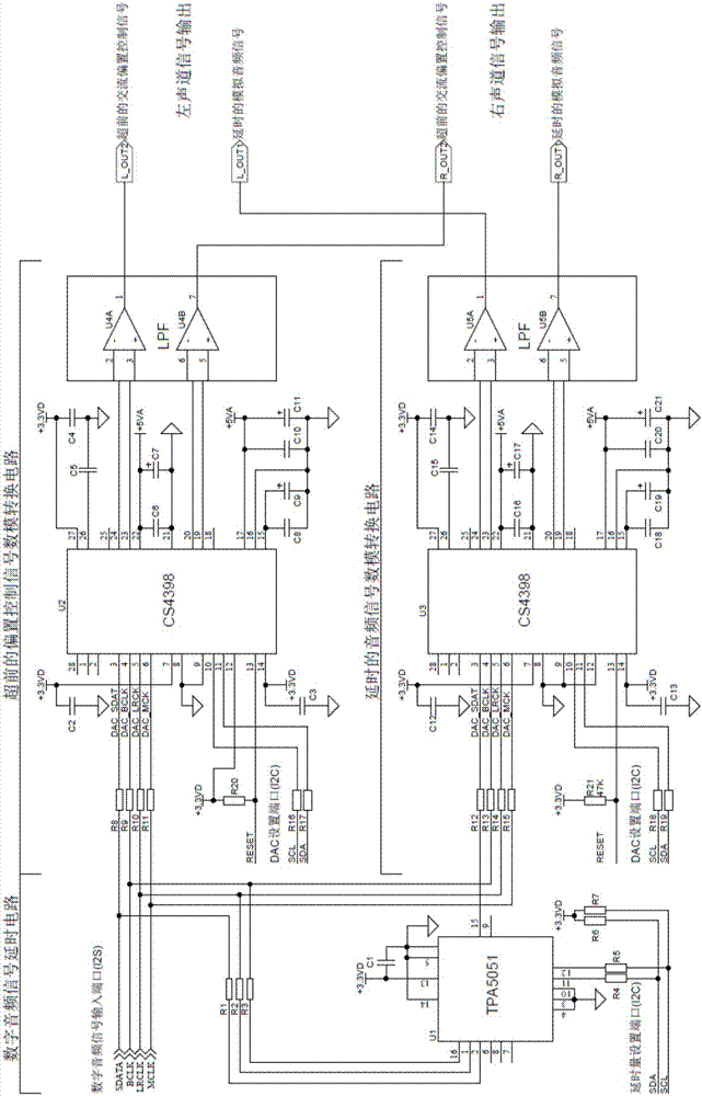
[0083] see image 3 and Figure 4 , a class A audio power amplifier, adopting the lead follow-up bias method of the present invention, is a kind of lead follow-up bias class A earphone power amplifier that simplifies the function and adopts one channel of two-channel IIS digital audio signal input , which includes: image 3 The digital audio signal delay circuit, the bias control signal digital-to-analog conversion circuit, the audio signal digital-to-analog conversion circuit, and Figure 4 Digital volume adjustment circuit, voltage amplifying circuit, full-wave rectification circuit, amplitude holding circuit, conversion circuit, voltage-controlled current bias circuit, power output circuit in the digital volume adjustment circuit; other necessary A-class audio power amplifiers irrelevant to the present invention The configuration, such as: input selection circuit, S / PDIF receiving circuit, analog-to-digital conversion circuit, power supply circuit, display circuit, contro...


PUM


Abstract

An advanced servo bias method of an A-class audio power amplifier and an amplifier. The advanced servo bias method relates to delaying a selected audio signal to be amplified and using an analog audio signal corresponding to the delayed audio signal as an audio signal which is to be input into a power amplifier for amplification. Moreover, the analog audio signal corresponding to the selected audio signal to be amplified is used for controlling to generate a bias that changes along with the amplitude of the delayed audio signal, and making a power amplification output circuit be in an A-class working state. An amplifier comprises a voltage or current bias circuit (112), a full wave rectification circuit (115), an amplitude holding circuit (114), a conversion circuit (113), an audio power amplification output circuit (111), and a delay circuit (108); The audio signal to be amplified is delayed and then enters the audio power amplification output circuit (111); after circuit processing, the analog audio signal corresponding to the audio signal to be amplified is used for controlling the output of a bias voltage or current of the voltage or current bias circuit (112). The amplifier can reduce a bias in due time, thereby reducing power consumption.

Description

technical field [0001] The invention relates to the field of audio power amplification, in particular to a leading follow-up bias method of a class A audio power amplifier and a class A audio power amplifier using the method. Background technique [0002] At present, with the development of multimedia technology, home audio power amplifiers, professional audio power amplifiers, car audio audio power amplifiers, and portable multimedia equipment audio power amplifiers are all developing rapidly, which can be divided into A, B, AB, D, G, H and other types. [0003] Among them, in the class B audio power amplifier, the power amplifier output tube is cut off half of the time in the entire signal cycle. Although the theoretical efficiency can reach 78.5%, there is a serious crossover distortion problem, and the playback sound is very bad. ; Class AB audio power amplifier, the power amplifier output tube is fully conductive when the signal is small and medium, and works in the wa...

Claims


Application Information

Patent Timeline
Patent Type & Authority Patents(China)
IPC IPC(8): H03F1/02H03F1/32H03F3/187H03F3/60H04R3/00
CPCH03F1/02H03F1/32H03F3/60
Inventor 叶鼎黄耀红周卫平
Owner 叶鼎
Why Eureka
Try Eureka