
Honey extracting device

A kind of equipment and technology of honey bucket, which is applied in A01K59/00: the field of honey collection, which can solve the secondary pollution of honey, thrown out, the larvae first break through the wax seal layer and then hit the wall of the honey bucket, and the larvae die, etc. question

Active Publication Date: 2016-12-14
正安县正江蜜蜂养殖场
View PDF6 Cites 1 Cited by
  • Summary
  • Abstract
  • Description
  • Claims
  • Application Information

AI Technical Summary

Problems solved by technology

When in use, the honeycomb is installed on the nest frame basket that is compatible with the barrel cavity of the honey shaker, and the honey shaker frame is placed in the honey shaker barrel, and the honey shaker frame is rotated by hand to use centrifugal force to shake off the honey on one side of the honeycomb. Then take out the honeycomb and rotate it 180 degrees and insert it on the frame to shake off the honey on the other side. The disadvantage of this kind of honey shaker is that when the centrifugal force is large, it is easy to throw out the larvae in the honeycomb, and the larvae break first. The wax seal layer then hits the wall of the honey bucket, causing the death of the larvae, and the larva corpses will be immersed in the honey in the honey bucket. The bacteria carried by the larvae will cause secondary pollution to the honey. Filtration to remove larvae

Method used


Image

  • Honey extracting device
  • Honey extracting device
  • Honey extracting device

Examples


Embodiment 1

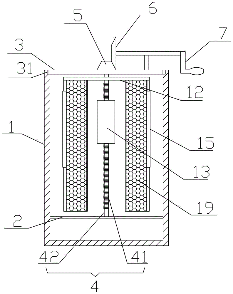
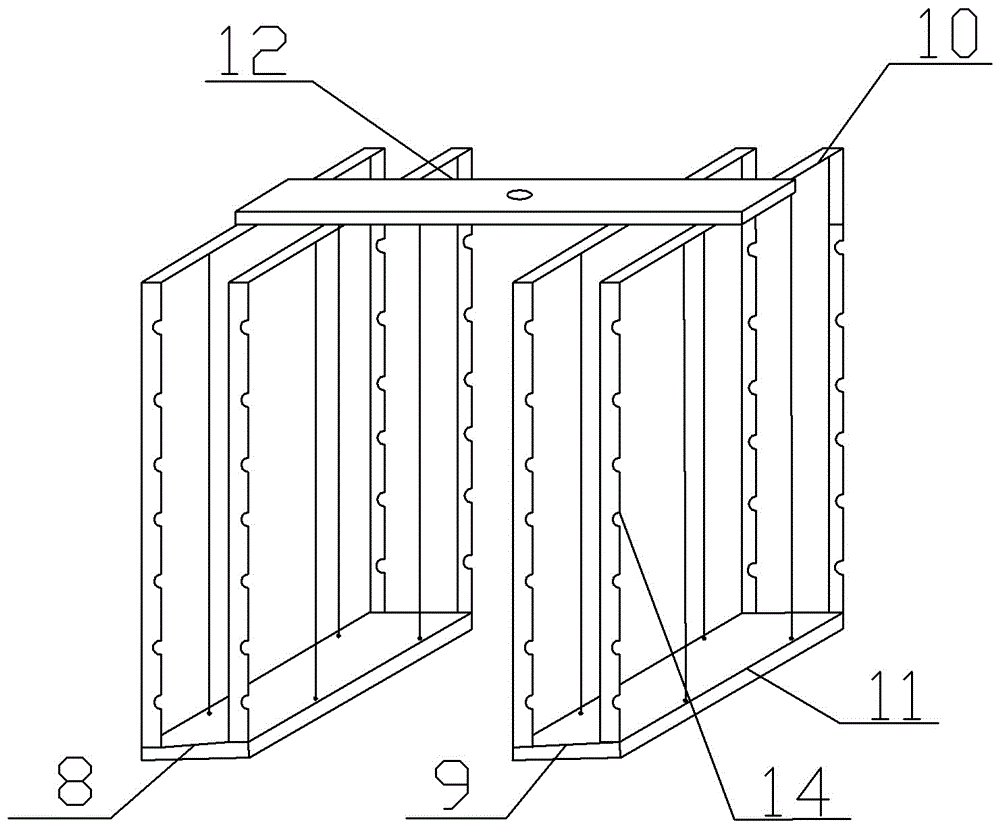
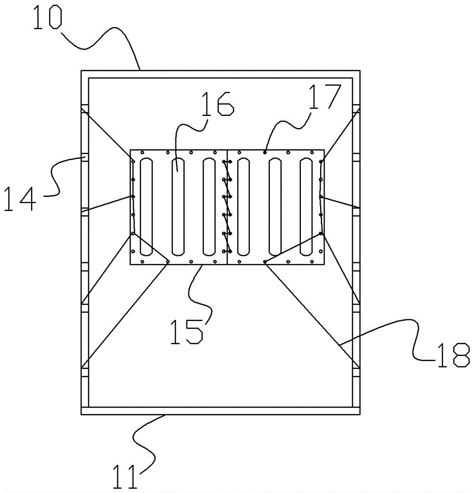
[0018] Embodiment 1: The equipment for shaking honey is basically as attached figure 1 , figure 2 , image 3 Shown: comprises the honey shake bucket 1 that is made of plastics, and the barrel wall of shake honey bucket 1 is bolt-connected with horizontal lower crossbeam 2, and this lower crossbeam 2 is 10cm higher than the bottom of shake honey bucket 1. There are two notches at the mouth of the honey bucket 1 along the radial direction of the mouth. The two ends of the upper beam 3 protrude to form legs 31 that can be placed in the notches. The upper beam 3 and the lower beam 2 are located on the same vertical direction.

[0019] The transmission shaft 4 is coaxial with the honey shaker 1, the lower end of the transmission shaft 4 is rotationally connected with the lower beam 2 through a ball bearing, and the upper end of the transmission shaft 4 penetrates the upper beam 3 and is connected with a flat key of the bevel gear 5, the bevel gear 5 The large surface of the beve...

Embodiment 2

[0030] Embodiment 2: The difference from Embodiment 1 is that the permanent magnet 13 is replaced by an electromagnet.


PUM


Abstract

The invention belongs to A01K 59 / 00: honey extracting technique. A honey extracting device includes a rocking barrel; a lower transverse beam is arranged on an inner wall of the rocking barrel; an upper transverse beam is arranged on a barrel opening of the rocking barrel; the upper end of a drive shaft passes through the upper transverse beam and is connected to a power structure, and the lower end of the drive shaft is rotatably connected to the lower transverse beam; a connection plate is fixed on the drive shaft; a left rocking frame and right rocking frame are fixed at two ends of the connection plate respectively; an anti-throwing sheet is provided, the anti-throwing sheet is formed by binding an inner layer and an outer layer, the outer layer projects at an equal distance to form cavities, iron powder is filled in the cavities, and suture holes are formed in edges of the anti-throwing sheet; binding grooves are formed in vertical portions of a U-shaped sheet frame at an equal distance; a silk thread passes through the suture holes of the anti-throwing sheet, and the silk thread is bound in the binding grooves; and a magnetic member is connected to the drive shaft. Through the anti-throwing sheet the attachment position of which can be changed, the situation that larva in a brood comb apiary is thrown away and dies can be prevented, and pollution to honey can be avoided.

Description

technical field [0001] The invention belongs to the field of A01K59 / 00: collecting honey technology. Background technique [0002] Honey is the nectar that bees collect from the flowers of flowering plants and brewed in the hive. It is a nutritious natural nourishing food and one of the most commonly used tonics. It has the functions of nourishing, moisturizing, detoxification, Whitening and other effects. The honeybee's nest is made of wax plates. Several plates hang from the upper part of the beehive to the lower part. On both sides of the board are arranged neat hexagonal cells called combs. The combs are embedded in easy-to-operate frames. Called the nest frame (comb frame). Honeycomb can be divided into powder spleen, honey spleen and sub-spleen. The structure and composition of these spleens are similar, but the functions and functions in the hive are different. The honeycomb stores the most honey in the hive. The sub-spleen is the place where there are the most lar...

Claims


Application Information

Patent Timeline
IPC IPC(8): A01K59/00
CPCA01K59/00
Inventor 高绍唐叶龚飞郑刚高云涛高浪
Owner 正安县正江蜜蜂养殖场
Learn More