Design method and device for bone cement spacer female mould

A technology of bone cement and spacer, which is used in medical science, prosthesis, joint implants, etc., can solve the problems of low precision, prolonged hemostasis time, and fast hardening speed of bone cement.

Inactive Publication Date: 2016-12-14
GUANGDONG UNIV OF TECH
View PDF7 Cites 2 Cited by
  • Summary
  • Abstract
  • Description
  • Claims
  • Application Information

AI Technical Summary

Problems solved by technology

However, there are still problems in the practical application of bone cement. First, most of the current bone cement spacers are made by doctors with bare hands, and the bone cement hardens quickly, so the manufacturing accuracy cannot be highly matched with human bones; second, the surgical process The producti

Method used


Image

  • Design method and device for bone cement spacer female mould
  • Design method and device for bone cement spacer female mould
  • Design method and device for bone cement spacer female mould

Examples


Embodiment 1

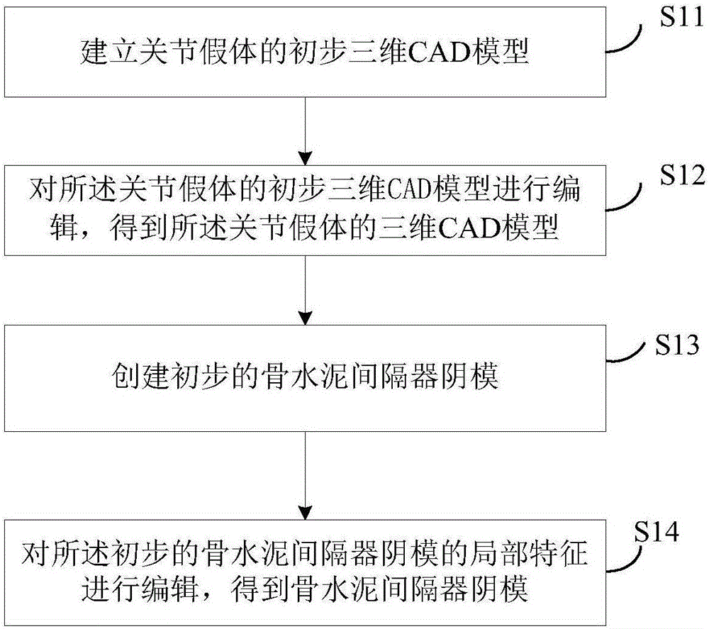
[0065] see figure 1 It is a schematic flow chart of a method for designing a bone cement spacer female mold provided in Embodiment 1 of the present invention. The method includes the following steps:

[0066] S11. Establish a preliminary three-dimensional CAD model of the joint prosthesis according to the collected point cloud data of the patient's joint prosthesis;

[0067] Among them, in the general understanding, the point data geometry of the product appearance surface obtained by measuring instruments in reverse engineering is also called point cloud. Usually, the number of points obtained by using a three-dimensional coordinate measuring machine is relatively small, and the relationship between points and points The spacing is also relatively large, which is called a sparse point cloud; while the number of points in the point cloud obtained by using a 3D laser scanner or a photo scanner is relatively large and dense, it is called a dense point cloud. In an embodiment of...

Embodiment 2

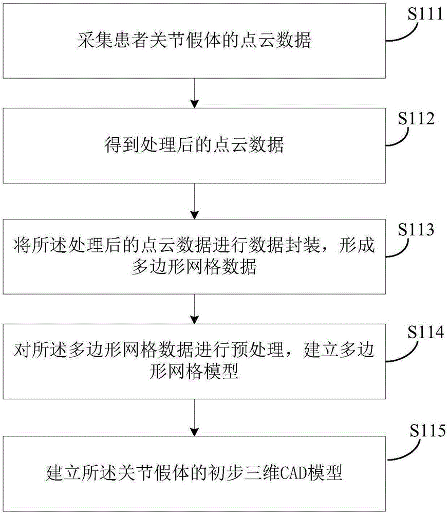
[0076] Referring to embodiment one of the present invention and figure 1 The specific process of steps S11 to S14 described in , and see figure 2 Corresponding to the second embodiment of the present invention figure 1 The schematic flow chart of the preliminary three-dimensional CAD model of establishing joint prosthesis in the shown S11 step, figure 1 Step S11 specifically includes:

[0077] S111, collecting point cloud data of the patient's joint prosthesis;

[0078] S112. Pre-processing redundant point clouds or noise points in the point cloud data to obtain processed point cloud data;

[0079] Specifically, due to the limitation of the scanning technology of the scanner and the influence of the scanning environment, it is inevitable to bring redundant point clouds or prematures. These point clouds can be manually selected to be deleted, and the scanned point cloud data must be aligned and reduced. Noise filtering and streamlining, etc., for subsequent processing.

...

Embodiment 3

[0104] Corresponding to the design method of the female mold of the bone cement spacer disclosed in the first and second embodiments of the present invention, the third embodiment of the present invention also provides a design device for the female mold of the bone cement spacer, see Figure 6 A schematic structural view of the design device for the bone cement spacer female mold provided in Embodiment 3 of the present invention, and Figure 7 It is a schematic structural diagram of the first establishment unit provided in Embodiment 3 of the present invention. The device specifically includes:

[0105] The first building module 31 is used to establish a preliminary three-dimensional CAD model of the joint prosthesis according to the collected point cloud data of the patient's joint prosthesis;

[0106] The first editing module 32 is used to edit the features other than the non-key curved surface of the preliminary three-dimensional CAD model of the joint prosthesis according...


PUM


Abstract

The invention discloses a design method and device for a bone cement spacer female mould. The design method for the bone cement spacer female mould includes: establishing a primary three-dimensional CAD model of a joint prosthesis according to acquired point cloud data of the joint prosthesis of a patient; obtaining a three-dimensional CAD model of the joint prosthesis according to the measured actual size of a joint of the patient; defining a joint surface of a relevant die of the three-dimensional CAD model of the joint prosthesis according to analysis on a connection manner and a working process of the three-dimensional CAD model of the joint prosthesis, and establishing a primary bone cement spacer female mould; and editing the primary bone cement spacer female mould to obtain the bone cement spacer female mould according to the characteristics of bone cement. The design method and device can quickly produce a high-precision high-matching-degree bone cement spacer female mould.

Description

technical field [0001] The invention relates to the technical field of artificial joint prosthesis design, in particular to a reverse engineering-based design method and device for a bone cement spacer female mold. Background technique [0002] An artificial joint prosthesis is an implant that is widely used in the joints of the human body such as hips, knees, shoulders and ankles. At present, the artificial joint prosthesis in my country is mainly imported from abroad. Since these prostheses are designed according to foreign anatomical standards, they may not match the shape and size of the articular surface of Chinese people. At the same time, for some metal, ceramic and other prostheses, some patients will have a strong rejection reaction, and it is difficult for patients with relatively serious tissue infection to apply such prostheses. After artificial joint replacement surgery, there will be a problem of postoperative infection. To treat postoperative infection, bone ...

Claims


Application Information

Patent Timeline
IPC IPC(8): A61F2/30
CPCA61F2/30A61F2002/30001A61F2/30942A61F2002/30952A61F2002/30957
Inventor 李明宇成思源胡召阔杨雪荣张湘伟
Owner GUANGDONG UNIV OF TECH
Why Eureka
Try Eureka