Hydraulic oscillator

A hydraulic oscillator and power technology, applied in vibration generating devices, wellbore/well components, earthwork drilling and production, etc., can solve the problems of increasing drilling tool friction, restricting drilling pressure, and easy deposition, etc., to improve friction Resistance, increase ROP, good vibration effect

Active Publication Date: 2016-12-14
四川保瑞特钻头有限公司
View PDF7 Cites 11 Cited by
  • Summary
  • Abstract
  • Description
  • Claims
  • Application Information

AI Technical Summary

Problems solved by technology

[0004] 1. Due to the large well deviation, the weight of the drill string in the direction of the borehole is small or nearly zero, so it is difficult to meet the pre-designed WOB;
[0005] 2. In horizontal wells, due to the large positive pressure of the drill string on the well wall due to its own weight, the friction of the drilling tool on the well wall is increased, thereby restricting the effective drilling pressure applied to the drill bit;
[0006] 3. For horizontal wells, since the horizontal section of construction is getting longer and longer, however, during the construction process of the well section with large well deviation, underpressure and sticking often occur;
[0007] 4. For compound drilling, especially in the sliding drilling process of downhole power tools, it is impossible to ensure that the real and effective WOB is applied to the drill bit, which seriously affects the average ROP and drilling cycle of the whole well.
[0008] The emergence of the above problems will lead to a small mud oscillation amplitude, easy to produce sedimentation, and finally the phenomenon of drilling tool sticking

Method used


Image

  • Hydraulic oscillator
  • Hydraulic oscillator
  • Hydraulic oscillator

Examples


Embodiment Construction

[0024] The present invention will be further described below in conjunction with the accompanying drawings, but the protection scope of the present invention is not limited to the following description.

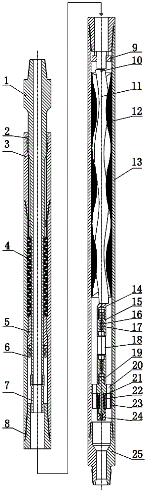
[0025] Such as figure 1 As shown, a hydraulic oscillator includes a mandrel 1, an upper joint 3, a disc spring 4, a mandrel middle joint 5, a mandrel lower joint 7, a screw pump, a disc valve group, an outer cylinder 13 and a lower joint 25, and the center The shaft 1 is a hollow cylinder structure, the mandrel 1 is inserted into the upper joint 3, the middle of the mandrel 1 is provided with a disc spring 4, the upper end of the disc spring 4 withstands the concave edge of the mandrel 1, and the lower end is pressed by the upper end of the mandrel joint 5 Tight, the joint 5 in the mandrel can move up and down, the lower end of the joint 5 in the mandrel is equipped with a piston 6, the lower joint 7 of the mandrel is arranged at the bottom of the mandrel 1, and the outer cyl...


PUM


Abstract

The invention relates to a hydraulic oscillator. The hydraulic oscillator comprises a mandrel, an upper connector, a disc spring, a mandrel middle connector, a mandrel lower connector, a screw rod pump, a disc valve set, an outer barrel and a lower connector, wherein the mandrel is inserted into the upper connector; the mandrel lower connector is arranged at the bottom of the mandrel; the outer barrel is composed of an upper sleeve and a lower sleeve; the screw rod pump is mounted in a connection short section; an output end of the screw rod pump is fixedly connected with the upper end of a rotor; a stator sleeves the outer side of the rotor; the lower end of the rotor is connected with the upper end of a universal shaft; the lower end of the universal shaft is connected with the disc valve set; and the lower connector is connected with the outer barrel through a thread. The hydraulic oscillator provided by the invention has the advantages that the screw rod pump can rotate only if flow exists and the sizes of holes on a flow through disc and a flow adjusting disc are changed periodically to generate an oscillating phenomenon; the loss of pressure drop energy of well drilling liquid is small and the energy of the well drilling liquid can be sufficiently utilized; and the hydraulic oscillator has a relatively good oscillating effect and the friction resistance of a drilling tool in a drilling bit rock breaking process is reduced, so that the well drilling efficiency is improved.

Description

technical field [0001] The invention relates to the technical field of drilling tools, in particular to a hydraulic oscillator. Background technique [0002] At present, oil field drilling has gradually developed from the original directional wells to horizontal wells. Due to the pressure of the drilling tools, the drilling tools are close to the lower side well wall during the horizontal drilling process, resulting in excessive friction of the drilling tools during the drilling process. , Seriously affect the drilling, and even cause the drill tool to depressurize and cannot be pressurized to the drill bit. Reducing friction, reducing sticking accidents in conventional drilling, increasing dynamic drilling pressure, and improving the efficiency of conventional drilling are problems that need to be solved urgently in current drilling projects. The study found that when the drilling tool passes through the mud, the mud pressure can change, which will cause the drilling tool ...

Claims


Application Information

Patent Timeline
Patent Type & Authority Applications(China)
IPC IPC(8): E21B28/00
CPCE21B28/00
Inventor 杨志孙阳鑫田家林
Owner 四川保瑞特钻头有限公司
Why Eureka
Try Eureka