
A drying room and a dehydration method using the drying room

A drying room and cold water technology, applied in drying, dryers, dryers for stationary materials, etc., can solve the problems of energy consumption, environmental damage, and low efficiency, and achieve the effect of low energy consumption and high efficiency

Active Publication Date: 2019-05-21
GUANGZHOU HUANGSHANGHUANG GRP
View PDF5 Cites 0 Cited by
  • Summary
  • Abstract
  • Description
  • Claims
  • Application Information

AI Technical Summary

Problems solved by technology

[0002] In the hot air drying method, there will be various heat losses, convective heat loss is one of them, convective heat refers to the relative displacement between various parts of the fluid caused by the macroscopic movement of the fluid, caused by the intermixing of cold and hot fluids Convection heat transfer can be divided into forced convection and natural convection. Forced convection is the circulation of fluid driven by external forces. Natural convection is due to the change of density gradient at different temperatures and gravity. Flow from top to bottom, high-temperature density fluid flows from bottom to top, the heat loss generated in the process of convective heat transfer is convective heat loss, the usual convective heat loss is latent heat, sensible heat enclosure heat in the drying process The sum of losses is more than twice, and the existing devices used to deal with the convective heat loss phenomenon only recover part of the heat discharged by convection, which has low efficiency, large energy consumption and environmental damage

Method used


Image

  • A drying room and a dehydration method using the drying room
  • A drying room and a dehydration method using the drying room

Examples


Embodiment 1

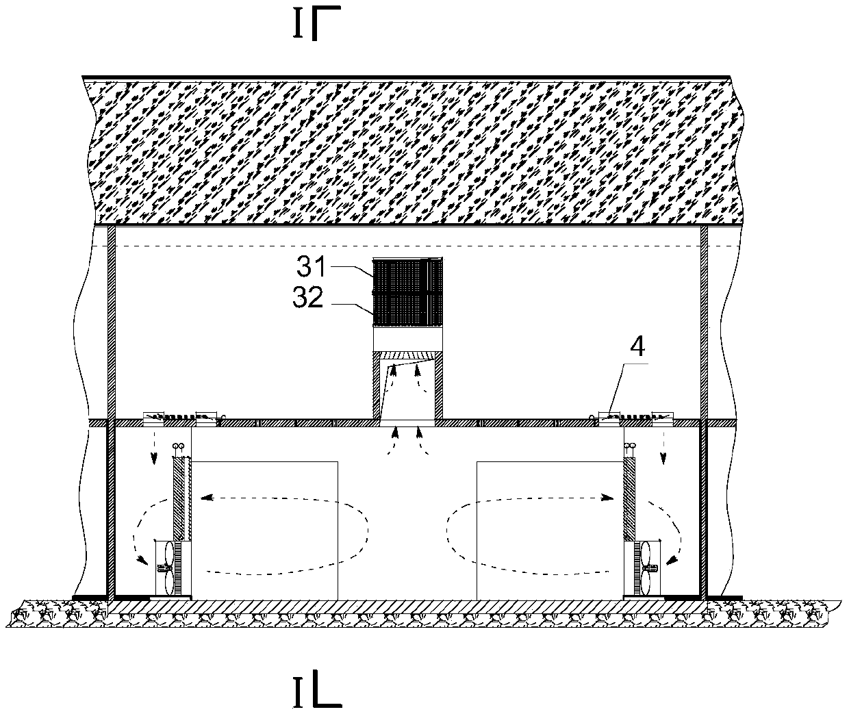
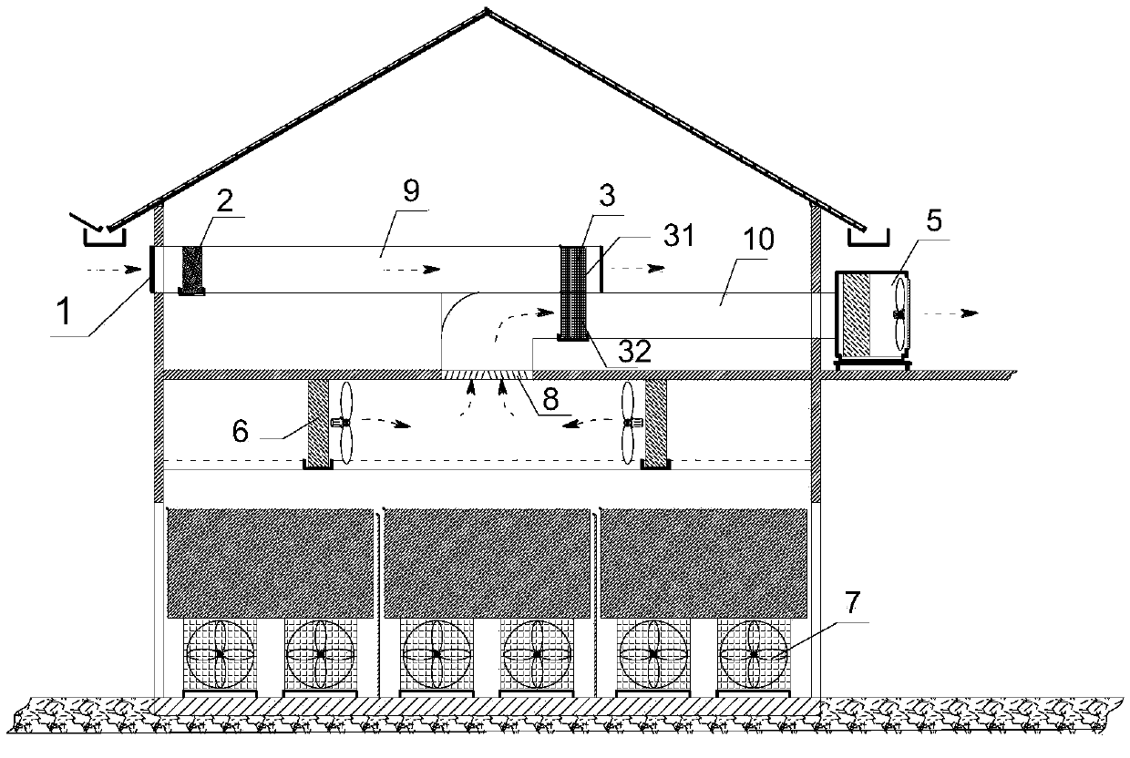
[0028] refer to Figure 1-2 , a drying room, including fresh air machine dew point cooler 2, oscillating heat pipe, double electric air valve 4, exhaust waste heat recovery wind cabinet 5, surface cooler 6 and fan 7.

[0029] The entrance of the drying room is provided with an air inlet 1, and the inside of the drying room is provided with an air outlet 8; the inlet air is connected to the air inlet end of the dew point cooler 2 of the fresh air machine, and the air outlet end of the dew point cooler 2 of the fresh air machine is connected to a second An air pipe 9, the other end of the first air pipe 9 is connected to the heat release end of the oscillating heat pipe;

[0030] The heat-absorbing end 32 of the oscillating heat pipe is connected to the double-connected electric air valve 4, the air outlet 8 is connected to the heat-absorbing end 32 of the oscillating heat pipe, and the heat-absorbing end 32 of the oscillating heat pipe is connected with the second air pipe 10, ...


PUM


Abstract

The invention discloses a drying room and a method for dehydration through the drying room. The drying room comprises an air freshening machine dew point cooler, an oscillating heat pipe, a duplex electric air valve, an exhaust air waste heat recovery wind cabinet, surface air coolers and fans; and an air inlet is formed in an entrance of the drying room, and an air exhaust port is formed in the drying room. The invention further provides the method for dehydration through the drying room. After entering the drying room, fresh air carries out heat exchange with the air freshening machine dew point cooler and then carries out heat exchange with the oscillating heat pipe, air on the top of the drying room carries out heat exchange with the surface air coolers and then carries out heat exchange with the oscillating heat pipe, and therefore the air can be cooled; and heat of cold water is absorbed after the cold water passes through the air freshening machine dew point cooler, the surface air coolers and the oscillating heat pipe, and therefore energy-saving production of air dehydrating and drying can be realized.

Description

technical field [0001] The invention relates to the field of hot air drying equipment, in particular to a drying room and a dehydration method using the drying room. Background technique [0002] In the hot air drying method, there will be various heat losses, convective heat loss is one of them, convective heat refers to the relative displacement between various parts of the fluid caused by the macroscopic movement of the fluid, caused by the intermixing of cold and hot fluids Convection heat transfer can be divided into forced convection and natural convection. Forced convection is the circulation of fluid driven by external forces. Natural convection is due to the change of density gradient at different temperatures and gravity. Flow from top to bottom, high-temperature density fluid flows from bottom to top, the heat loss generated in the process of convective heat transfer is convective heat loss, the usual convective heat loss is latent heat, sensible heat enclosure he...

Claims


Application Information

Patent Timeline
Patent Type & Authority Patents(China)
IPC IPC(8): F26B9/02F26B21/00F26B21/08F26B23/00
CPCF26B9/02F26B21/002F26B21/086F26B23/002Y02P70/10
Inventor 陈耀胡昕赵君何智阳梁嘉志
Owner GUANGZHOU HUANGSHANGHUANG GRP
Learn More