Large-dynamic range high-precision optical axis measurement device

A large dynamic range, measuring device technology, applied in the direction of measuring devices, optical devices, instruments, etc., can solve problems such as improving detection accuracy, and achieve the effect of improving detection accuracy and broadening detection

Active Publication Date: 2016-12-14
INST OF OPTICS & ELECTRONICS - CHINESE ACAD OF SCI
View PDF7 Cites 5 Cited by
  • Summary
  • Abstract
  • Description
  • Claims
  • Application Information

AI Technical Summary

Problems solved by technology

[0004] In order to ensure the dynamic range of the optical axis detection, while keeping the optical axis detection sensitivity unchanged, we can reduce the influence of noise and other factors on the optical axis accuracy through image processing, thereby improving the detection accuracy, the literature "Shack-Hartmann Selection of Image Adaptive Threshold of Wavefront Sensor, Optical Precision Engineering, 2010, 18(2)334, High-precision Measurement of Spot Centroid Based on Image Processing Technology, Optoelectronic Laser, 2011, 22(10)1542, etc. proposed various An algorithm to improve the accuracy of the centroid of the light spot, these algorithms improve the detection accuracy of the centroid to varying degrees, but the basis for improving the accuracy of these methods is to assume that the distribution of the light spot is symmetrical, such as Gaussian light spot or Airy disk, etc. From this Based on this assumption, the accuracy improvement brought by various algorithms is analyzed. These algorithms do not improve the detection accuracy by obtaining more input information in essence; the detection of the optical axis of the spot that does not meet the assumed conditions such as the input beam contains aberrations is not necessarily the case. efficient

Method used


Image

  • Large-dynamic range high-precision optical axis measurement device
  • Large-dynamic range high-precision optical axis measurement device
  • Large-dynamic range high-precision optical axis measurement device

Examples


Embodiment Construction

[0017] The present invention will be further described below in conjunction with the accompanying drawings and specific embodiments.

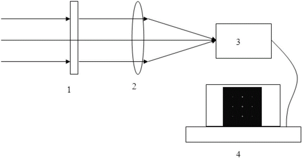
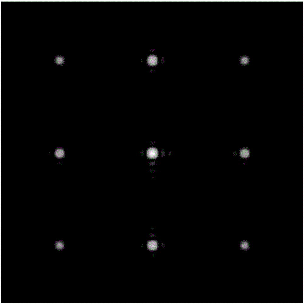
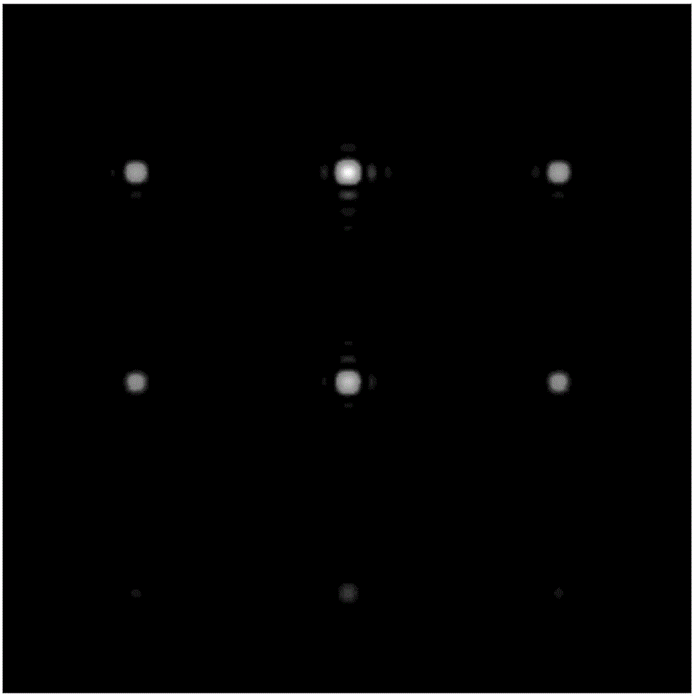
[0018] Such as figure 1 As shown, the present invention includes: a high-precision optical axis measurement device with a large dynamic range, which is composed of a two-dimensional spectroscopic module 1, an imaging module 2, a far-field recording module 3 and a far-field centroid calculation module 4, wherein the far-field recording module 3 includes Imaging CCDs and image recording devices. The far-field recording module 1 collects the light spot array and saves it in the memory of the far-field centroid calculation module 4 . The far-field centroid calculation module 4 calculates the centers Cx and Cy of the entire spot array according to the centroid calculation formula, and uses the center point to select the calculation area of ​​the central spot, and then obtains the surrounding 8 spots by translating the calculation area of ​​the cent...


PUM


Abstract

A large-dynamic range high-precision optical axis measurement device disclosed by the present invention is composed of a light beam splitting module, an imaging module, a far field recording module and a far field center of mass calculation module. After passing the light beam splitting module, an incident light beam is gathered by the imaging module at a focus position, the far field recording module acquires the light spot distribution, and the far field center of mass calculation module outputs an optical axis direction of the incident light beam. According to the present invention, a light splitting element segments the incident light beam into a plurality of light beams having the same incident direction, and the light spot detection information is increased, thereby improving the light spot detection precision. According to the present invention, by utilizing the light splitting element, the light spot distribution is greater than a target surface area, even though the light spots exceed the target surface area, the optical axis offset of the incident light beam still can be calculated by the intensity distribution of a light spot array, thereby broadening the light spot detection.

Description

technical field [0001] The invention relates to an optical axis measuring device, in particular to a high-precision optical axis measuring device with a large dynamic range. Background technique [0002] Optical axis detection with high precision and large dynamic range is an important branch of optical axis detection, especially for the detection of optical axis alignment in adaptive optics. Micro-radian alignment accuracy is required; however, the realization of large dynamic range and high-precision detection is essentially a pair of contradictory processes, and a multi-level decomposition detection method is generally used to approach the above detection process. When the optical axis deviates far away, a detection method with a large dynamic range and low detection accuracy is used; when the optical axis is close to the center, a high-precision detection device is used, and the dynamic range of detection is small at this time. [0003] The detection range of the optica...

Claims


Application Information

Patent Timeline
Patent Type & Authority Applications(China)
IPC IPC(8): G01B11/27
CPCG01B11/272
Inventor 黄林海陈林
Owner INST OF OPTICS & ELECTRONICS - CHINESE ACAD OF SCI
Why Eureka
Try Eureka