Cooling device for motor of engraving machine
A cooling device and electromechanical technology, applied in the field of engraving machines, can solve the problems of high physical loss of personnel, inflexible turning angle of the flexible shaft, and large belt transmission noise, so as to reduce the maintenance cost in the later stage, prevent life-threatening, and increase the speed The effect with power
- Summary
- Abstract
- Description
- Claims
- Application Information
AI Technical Summary
Problems solved by technology
Method used
Image

Examples
Embodiment 1
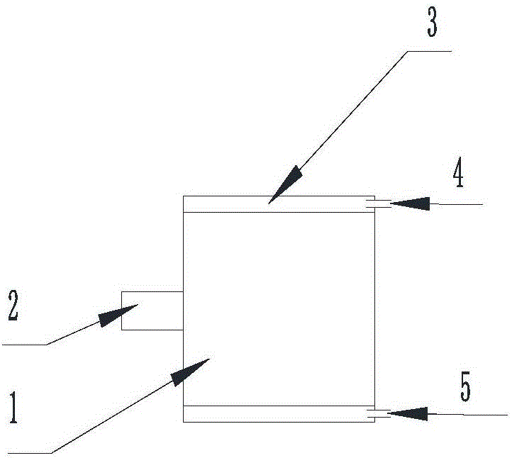
[0032] see figure 1 , the embodiment of the present invention is provided with a motor 1, and a coolant cooling mechanism in the motor housing is provided on the motor housing.
[0033] The motor housing of the cooling liquid cooling mechanism in the described motor housing is provided with a cavity 3, and the cavity 3 is provided with a cooling liquid inlet 4 and a cooling liquid outlet 5, and the cooling liquid inlet 4 and the cooling liquid source cooling liquid outlet ( Not shown in the figure) is connected, and the cooling liquid outlet 5 is connected with the cooling liquid inlet (not shown in the figure) of the cooling liquid source through pipelines, and the cooling liquid can adopt water, and the cooling liquid source can adopt a pond with a pump.
Embodiment 2
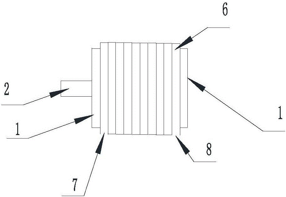
[0035] see figure 2 , the embodiment of the present invention is provided with motor 1, is provided with the motor housing peripheral helical cooling liquid tube cooling mechanism on the motor housing, the spiral cooling liquid of the motor housing peripheral helical cooling liquid tube cooling mechanism The pipe 6 is close to the outer periphery of the housing of the motor 1, the coolant inlet 7 of the spiral coolant pipe 6 is connected to the coolant source coolant outlet (not shown in the figure), and the coolant outlet 8 of the spiral coolant pipe is connected to the Coolant source inlet (not shown in the figure) is connected. The coolant can be antifreeze, and the source of the coolant can be an antifreeze tank.
[0036] The cross-section of the spiral cooling liquid pipe 6 can be circular, square, crescent-shaped, etc., preferably crescent-shaped, so as to increase the contact surface between the spiral cooling liquid pipe 6 and the housing of the motor 1 .
Embodiment 3
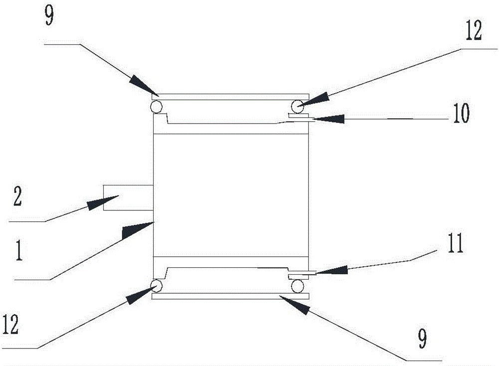
[0038] see image 3 , the embodiment of the present invention is provided with motor 1, is provided with motor housing peripheral coolant jacket cooling mechanism on motor casing, and the coolant jacket 9 of described motor casing peripheral coolant jacket cooling mechanism is set on motor 1 On the outer periphery of the housing, the coolant jacket 9 is provided with a coolant inlet 10 and a coolant outlet 11, the coolant inlet 10 is connected to the coolant source coolant outlet (not shown in the figure), and the coolant outlet 11 is connected to the coolant outlet. The source coolant inlet (not shown in the figure) is connected; a sealing ring 12 is provided between the coolant jacket 9 and the housing of the motor 1 . The coolant can be oil, and the source of the coolant can be an oil tank.
[0039] exist Figure 1~3 Among them, mark 2 is the motor shaft.
PUM
 Abstract
Description
Claims
Application Information
 - Generate Ideas
- Intellectual Property
- Life Sciences
- Materials
- Tech Scout
- Unparalleled Data Quality
- Higher Quality Content
- 60% Fewer Hallucinations
Browse by: Latest US Patents, China's latest patents, Technical Efficacy Thesaurus, Application Domain, Technology Topic, Popular Technical Reports.
© 2025 PatSnap. All rights reserved.Legal|Privacy policy|Modern Slavery Act Transparency Statement|Sitemap|About US| Contact US: help@patsnap.com