
SCR urea solution mixer and inner tube assembly thereof

A solution mixing, inner tube technology, applied in mixers, dissolving, engine components, etc., can solve the problems of urea droplets not being converted in real time, affecting the consistency and conversion efficiency of NOx emissions, and unstable reduction reactions.

Inactive Publication Date: 2016-12-21
WEICHAI POWER CO LTD
View PDF4 Cites 9 Cited by
  • Summary
  • Abstract
  • Description
  • Claims
  • Application Information

AI Technical Summary

Problems solved by technology

During the operation of the vehicle, due to poor atomization of urea, uneven mixing or insufficient decomposition, the sprayed urea droplets cannot be converted into NH3 in real time, but generate by-products, resulting in unstable reduction reaction , thus affecting the consistency and conversion efficiency of NOx emissions

Method used


Image

  • SCR urea solution mixer and inner tube assembly thereof
  • SCR urea solution mixer and inner tube assembly thereof
  • SCR urea solution mixer and inner tube assembly thereof

Examples


Embodiment Construction

[0030] The core of the present invention is to provide an inner tube assembly of an SCR urea solution mixer to improve the mixing uniformity of the urea solution, promote the full utilization of the urea solution, and ultimately reduce the problem of excessive deposition of urea;

[0031] Another core of the present invention is to provide an SCR urea solution mixer.

[0032] Hereinafter, an embodiment will be described with reference to the drawings. In addition, the examples shown below do not limit the content of the invention described in the claims in any way. In addition, all the contents of the configurations shown in the following embodiments are not limited to be essential to the solution of the invention described in the claims.

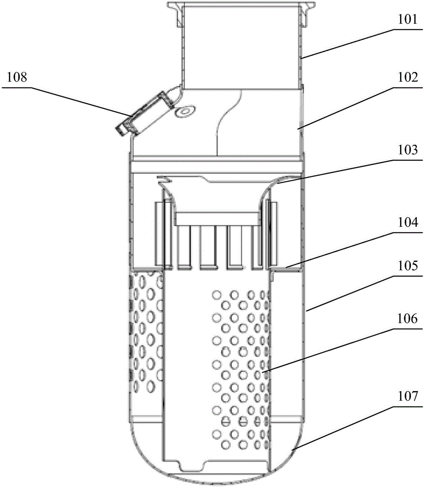
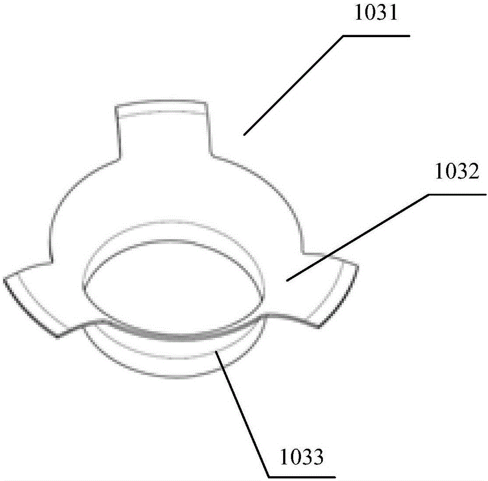
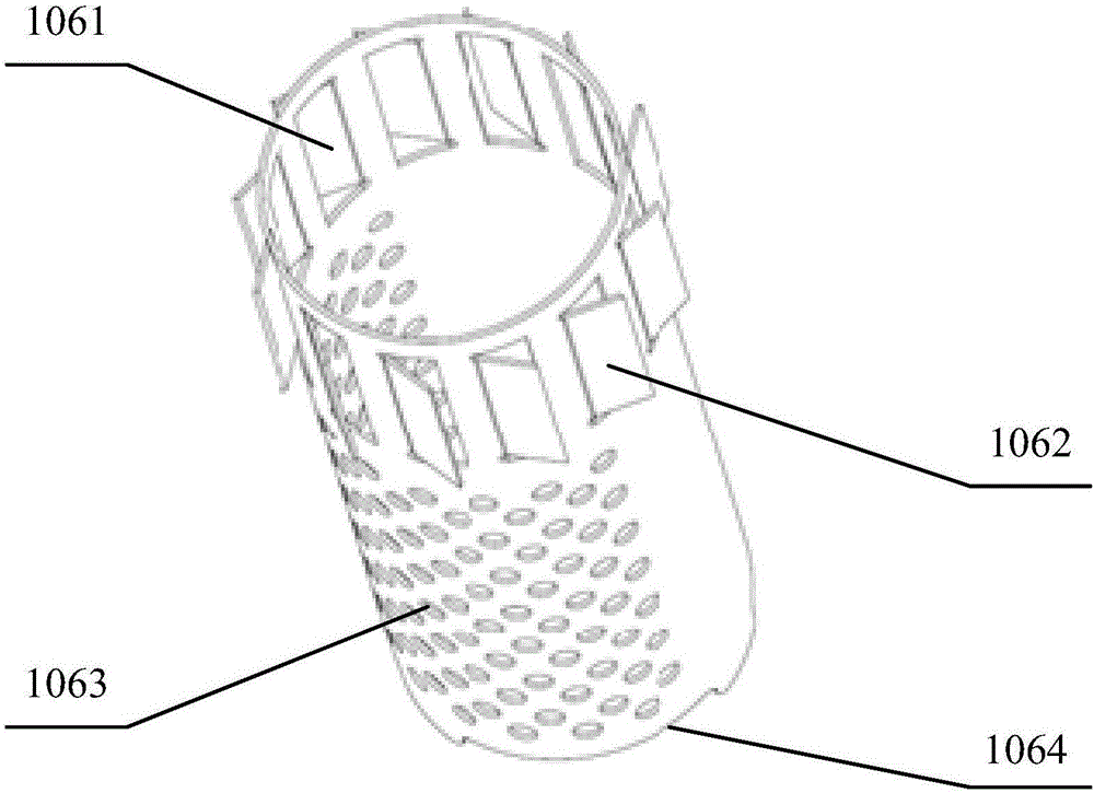
[0033] see figure 1 and image 3 , figure 1 Schematic diagram of the structure of the SCR urea solution mixer provided for the embodiment of the present invention; image 3 It is a schematic structural diagram of the inner tube provide...


PUM


Abstract

The embodiment of the invention discloses an SCR urea solution mixer inner tube assembly which comprises an inner tube and a baffle cover. Airflow inlets of the inner tube comprise an end hole located at one end of the inner tube and side wall holes formed in the side wall of the inner tube, the side wall holes are close to the end hole, and a swirl plate used for producing swirling flow is arranged on one side of each side wall hole; the baffle cover is arranged on the outer side of the inner tube so as to block airflow, and the airflow can only enter the inner tube through the end hole and the side wall holes. According to the SCR urea solution mixer inner tube assembly, due to the fact that by means of the swirl effect of the swirl plates, the flow velocity of the airflow entering the inner tube is higher, tail gas and a urea solution are mixed to be more uniform, full utilization of the urea solution is promoted, and reduction of overdeposition of urea is finally achieved. The invention further discloses an SCR urea solution mixer.

Description

technical field [0001] The invention relates to the technical field of mixers, in particular to an SCR urea solution mixer and an inner tube assembly thereof. Background technique [0002] The basic principle of SCR (Selective Catalytic Reduction, selective catalytic reduction technology) technology is to inject fuel or add other reducing agents to the exhaust, select a suitable catalyst, and promote the reduction of the reducing agent and NO x reaction while inhibiting the oxidation of the reducing agent by oxygen in the exhaust. According to the type of reducing agent, the existing SCR technology can be divided into NH produced by the decomposition of urea 3 There are two types of urea SCR technology as reducing agent and hydrocarbon SCR technology using hydrocarbon as reducing agent. At present, the hydrocarbon SCR technology is still under further research, and there are not many practical applications; while the urea SCR technology is relatively mature, and there are ...

Claims


Application Information

Patent Timeline
IPC IPC(8): B01F13/02B01D53/94F01N3/20B01F33/40
CPCB01D53/9418F01N3/2066B01D2251/2067B01D2251/2062B01F33/404B01F33/409B01F33/402B01F33/4094Y02T10/12
Inventor 王意宝张蒿王奉双王东升张晓丽张素英解家报
Owner WEICHAI POWER CO LTD
Learn More