Supercharge Your Innovation With Domain-Expert AI Agents!

Intelligent mechanical automatic H-shaped steel component welding and conveying mechanism

A technology of intelligent machinery and conveying mechanism, applied in the field of welding of steel components, can solve the problems of high risk factor, high labor intensity of operators, low production efficiency, etc., and achieve the effect of low labor intensity

Active Publication Date: 2016-12-21
ANHUI HONGLU STEEL CONSTR (GROUP) CO LTD
View PDF9 Cites 0 Cited by
  • Summary
  • Abstract
  • Description
  • Claims
  • Application Information

AI Technical Summary

Problems solved by technology

[0002] In the existing welding production line of H-shaped steel components, the feeding and discharging are manually operated and hoisted, and the welding torch is manually aimed at the weld seam during welding. During the welding process, the welding torch needs to be adjusted manually so that the welding torch is always aligned with the weld seam, and the workpiece The overturning is hoisted by driving, and the labor intensity of the operators is high; the workpiece is turned over by manual operation, which has a high risk factor; the single-wire submerged arc automatic welding is used, especially for thick plate welding, and the production efficiency is low.

Method used


Image

  • Intelligent mechanical automatic H-shaped steel component welding and conveying mechanism
  • Intelligent mechanical automatic H-shaped steel component welding and conveying mechanism
  • Intelligent mechanical automatic H-shaped steel component welding and conveying mechanism

Examples


Embodiment Construction

[0021] The present invention will be described in further detail below in conjunction with the accompanying drawings and specific embodiments.

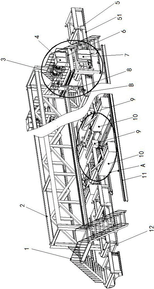
[0022] An intelligent mechanical automation H-shaped steel component welding delivery mechanism, such as figure 1 As shown, including H-shaped steel component moving mechanism and welding gantry moving mechanism;

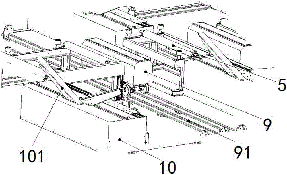
[0023] The moving mechanism of the H-shaped steel component includes a component moving track 51, on which the component moving track 51 is provided with a cylindrical automatic feeding roller table 5 and a cylindrical component sending roller table 12, and the automatic feeding roller table 5 and the component sending out An automatic translation lifting device 9 and an automatic turning machine 10 are arranged between the roller tables 12; the automatic translation lifting device 9 can drive the H-shaped steel member to lift and can slide laterally on the translation slide rail 91; the automatic turning machine 10 is prov...


PUM

PropertyMeasurementUnit
Section widthaaaaaaaaaa
Lengthaaaaaaaaaa

Abstract

The invention discloses an intelligent mechanical automatic H-shaped steel component welding and conveying mechanism which comprises an H-shaped steel component moving mechanism and a welding portal frame moving mechanism. The H-shaped steel component moving mechanism comprises a component moving rail with a cylindrical automatic feeding roller table and a cylindrical component send-out roller table, and automatic translation lifting equipment and an automatic overturning machine are arranged between the cylindrical automatic feeding roller table and the cylindrical component send-out roller table. The welding portal frame moving mechanism comprises a steel structure truss and a welding portal frame traveling rail, and a movable welding portable frame is mounted between the steel structure truss and the welding portal frame traveling rail. The component moving rail comprises 3-5 units, each unit is used for conveying one H-shaped steel component, and when a certain H-shaped steel component is transported to the automatic translation lifting equipment, all units stop working except for the unit where the H-shaped steel component is positioned. The intelligent mechanical automatic H-shaped steel component welding and conveying mechanism has advantages that automatic feeding and discharging are realized, manual intervention is avoided in a welding process, automatic overturning and welding of workpieces are realized, and labor intensity is low; operators are away from the workpieces in the welding process, so that the danger coefficient in production is zero nearly.

Description

technical field [0001] The invention relates to the technical field of steel component welding, in particular to an intelligent mechanical automation H-shaped steel component welding delivery mechanism. Background technique [0002] In the existing welding production line of H-shaped steel components, the feeding and discharging are manually operated and hoisted, and the welding torch is manually aimed at the weld seam during welding. During the welding process, the welding torch needs to be adjusted manually so that the welding torch is always aligned with the weld seam, and the workpiece The overturning is hoisted by driving, and the labor intensity of the operators is high; the workpiece is turned over by manual operation, which has a high risk factor; the single-wire submerged arc automatic welding is used, especially for thick plate welding, and the production efficiency is low. Contents of the invention [0003] The object of the present invention is to provide a kin...

Claims


Application Information

Patent Timeline
IPC IPC(8): B23K37/047B23K37/02
CPCB23K37/0211B23K37/047
Inventor 袁庆周吴振国张亚军
Owner ANHUI HONGLU STEEL CONSTR (GROUP) CO LTD
Features
  • R&D
  • Intellectual Property
  • Life Sciences
  • Materials
  • Tech Scout
  • Unparalleled Data Quality
  • Higher Quality Content
  • 60% Fewer Hallucinations
Learn More