Follow-up scraping mechanism for removing adhesion objects on anode plates

A technology for anode plates and adherents, applied in the direction of electrochemical sludge treatment, special treatment targets, dehydration/drying/concentrated sludge treatment, etc., can solve the problem of increasing adherents, surface damage of anode plates, increased scraping and Difficulty and other issues, to achieve the effect of simple follow-up structure and easy production

Inactive Publication Date: 2016-12-21
江苏百新环境工程有限公司
View PDF5 Cites 0 Cited by
  • Summary
  • Abstract
  • Description
  • Claims
  • Application Information

AI Technical Summary

Problems solved by technology

In fact, the anode plate of the circular transmission will naturally relax after running for a period of time. Once the load is too large, the position of the anode plate will change, and even cause the anode plate to collide with the scraping mechanism with a fixed position.
This kind of hard collision is easy to cause damage to the surface of the anode plate. After the surface of the damaged anode plate is rough, the amount of adhesions will be further increased, and the amount of scraping and difficulty will also be increased.
Generally speaking, the installation position of the scraping mechanism configured in the prior art is fixed, and it changes asynchronously with the slightly floating anode plate in the installation position, which is the root cause of the mutual collision problem

Method used


Image

  • Follow-up scraping mechanism for removing adhesion objects on anode plates
  • Follow-up scraping mechanism for removing adhesion objects on anode plates

Examples


Embodiment Construction

[0014] The present invention will be further described below according to the accompanying drawings and in conjunction with the embodiments.

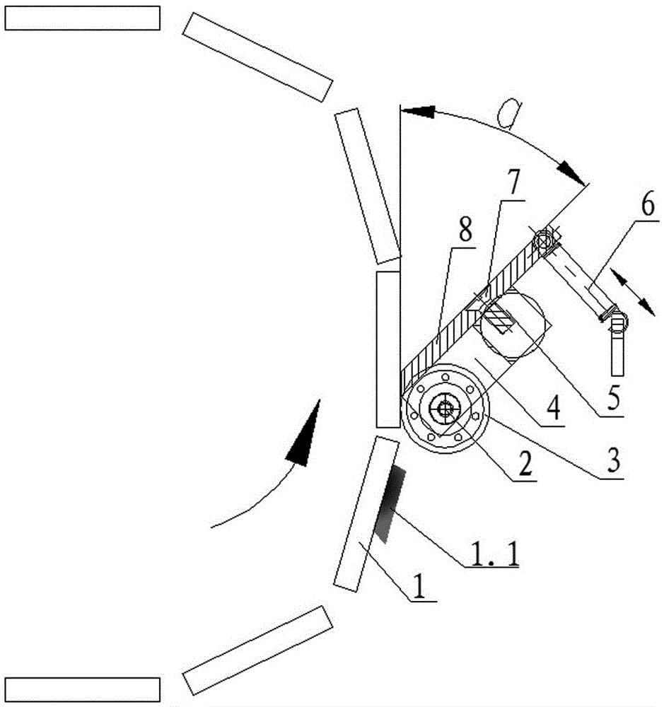
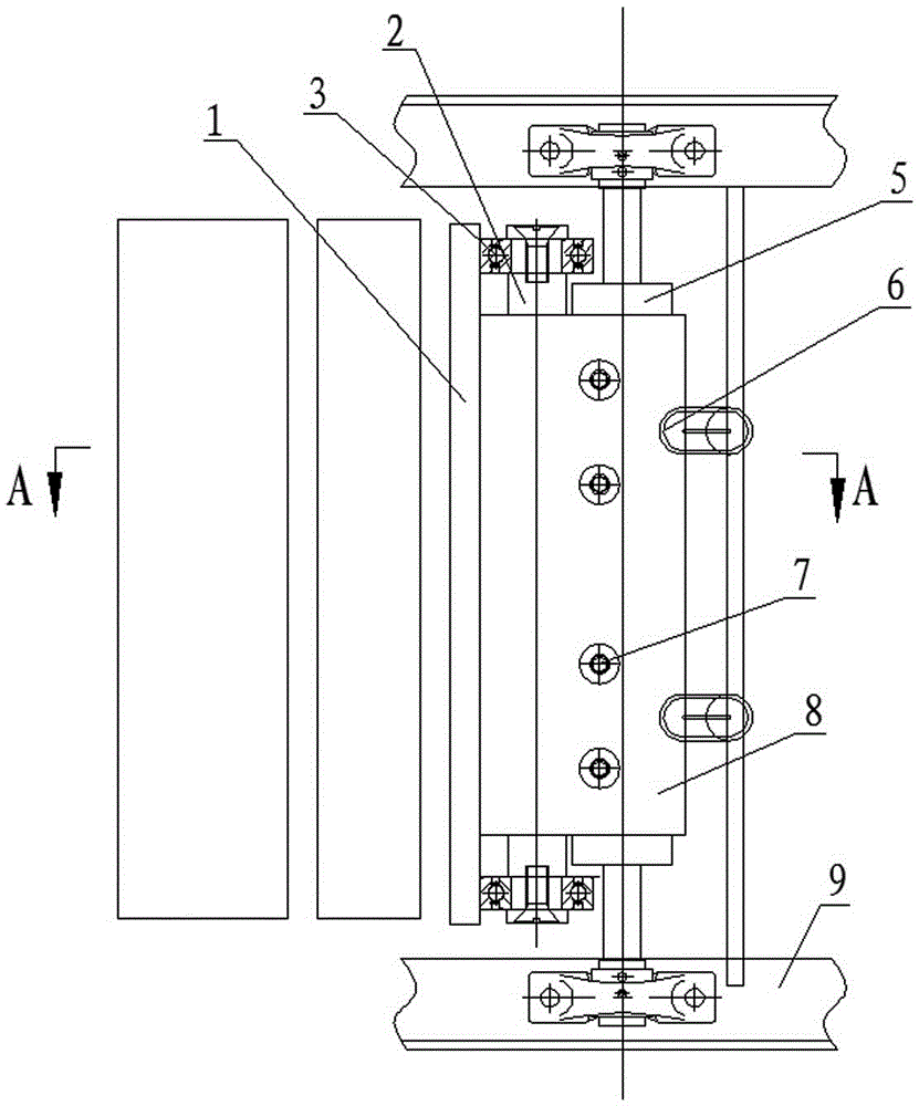
[0015] The follow-up scraping mechanism for removing anode plate adherents shown in the accompanying drawings is configured in the electro-osmotic sludge dewatering equipment, which includes an anode plate 1, a positioning shaft 2, a bearing 3, a plate 4, a knife shaft 5, a spring 6, Screw 7, scraper 8 and frame 9. The cutter shaft 5 is a slender shaft, the round shaft sections at both ends are equipped with bearing seats, and the middle section is a rectangular shaft section. The cutter shaft 5 straddles the supporting equipment frame 9 and is connected by a bearing seat, and the middle rectangular shaft section is connected with a plate-shaped scraper 8 by a screw 7 . The scraper 8 is inclined relative to the front surface of the matched anode plate 1, and the inclination angle α is an acute angle, and the inclination angle α=30° in ...


PUM


Abstract

The invention discloses a follow-up scraping mechanism for removing adhesion objects on anode plates. The follow-up scraping mechanism comprises the anode plates, a positioning shaft, bearings, a plate block, a cutter shaft, springs, screws, a scraper and a machine frame, wherein the cutter shaft is crossed on the machine frame; the scraper is fixedly connected to the cutter shaft; the plane of the scraper is matched with the obverse plate surfaces of the anode plates in an acute angle; the positioning shaft is placed between the obverse plate surfaces of the anode plates and the cutter shaft in a parallel manner, and the bearings assembled at two ends of the positioning shaft roll along non-work surfaces at two ends of each anode plate; the plate block is connected with the positioning shaft and the cutter shaft; a gap of 0.2-0.5 mm is reserved between the cutting edge of the scraper and the obverse plate surface of each anode plate matched with the scraper in the structure; and the springs are located between the external extending end of the scraper and a crossbeam of the machine frame, and in the scraping mechanism, the scraper moves along with the anode plates through the dragging of the springs. According to the follow-up scraping mechanism disclosed by the invention, the purpose that the scraper is not in contact with the anode plates is really achieved, the situation that the surfaces of the anode plates are not damaged is guaranteed, and bright and clean anode plates facilitate the high-efficient removal of the adhesion objects by the follow-up scraping mechanism.

Description

technical field [0001] The technology involved in the present invention belongs to the technical field of environmental protection machinery. Specifically, the present invention relates to a pole plate scale cleaning mechanism in an electro-osmotic sludge dewatering device, especially an electro-osmotic sludge dewatering device configured to remove anode plate adherents. Follow-up scraping mechanism. Background technique [0002] The anode plate is the core component of the electro-osmotic sludge dewatering equipment. It is not only the transmission part that directly carries the sludge, but also one of the power parts for mechanical pressing. The most important thing is that the anode plate is actually an electrode. The sludge carried in the dehydration process is ionized, and some of the impurities are adsorbed on the anode plate along with the flow of electrons, resulting in the situation that part of the dehydrated sludge is not easy to peel off from the anode plate. On...

Claims


Application Information

Patent Timeline
Patent Type & Authority Applications(China)
IPC IPC(8): C02F11/12
CPCC02F11/006C02F11/12C02F2303/06C02F2303/14
Inventor 张宪如杨淑兵张慧方世峰
Owner 江苏百新环境工程有限公司
Why Eureka
Try Eureka