A turbocharger axial force measurement system and its testing method

A turbocharger and measurement system technology, applied in the direction of force/torque/power measuring instruments, measuring devices, instruments, etc., can solve the problems of increased cost, complex structure, and large difference in the axial force of turbine blades, etc., to achieve reduction The effect of experimental error, fast transient response and high sensitivity

Active Publication Date: 2019-01-15
NINGBO WEIFU TIANLI TURBOCHARGING TECH
View PDF10 Cites 0 Cited by
  • Summary
  • Abstract
  • Description
  • Claims
  • Application Information

AI Technical Summary

Problems solved by technology

However, there are great limitations when this device is used to test the axial force of a turbocharger: first, a turbocharger is a high-speed rotating machine, and the speed of a turbocharger for a small car can reach up to 300,000 revolutions. The high-speed motor used in the device is difficult to realize. If a gearbox is used, not only the structure is complicated, the cost will increase, but more importantly, the accuracy of the axial force measurement results will be greatly reduced. Therefore, this general-purpose device is only suitable for low-speed rotating machinery
Second, when the turbocharger is working, the high-temperature gas (about 600-950°C) discharged from the engine enters the turbine to expand and do work. If a motor is used to drive the turbocharger to rotate, the working state of the turbine, that is, the pressure and temperature , intake air flow, etc. are all under the standard atmosphere, which is completely different from the actual working state of the engine. At this time, the axial force on the turbine blades is also very different. Therefore, the test results cannot truly reflect the working state of the turbocharger. In the case of axial forces in the state, the measurement results are meaningless
However, due to the compact structure of the small turbocharger, the selection of the sticking position of the strain gauge and the sticking reliability become the key difficulties affecting the measurement results

Method used


Image

  • A turbocharger axial force measurement system and its testing method
  • A turbocharger axial force measurement system and its testing method
  • A turbocharger axial force measurement system and its testing method

Examples


Embodiment Construction

[0053] The present invention will be further described in detail below in conjunction with the accompanying drawings and specific embodiments.

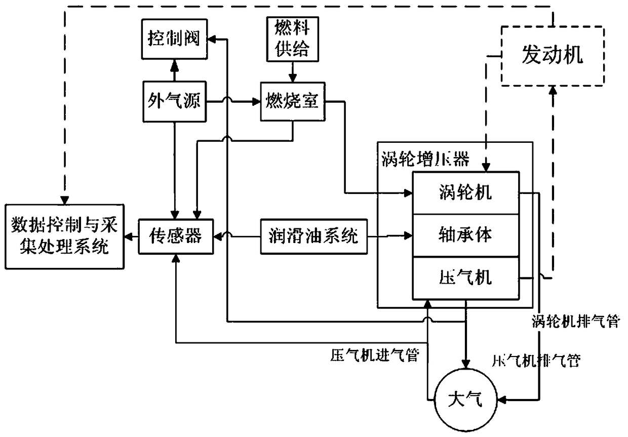
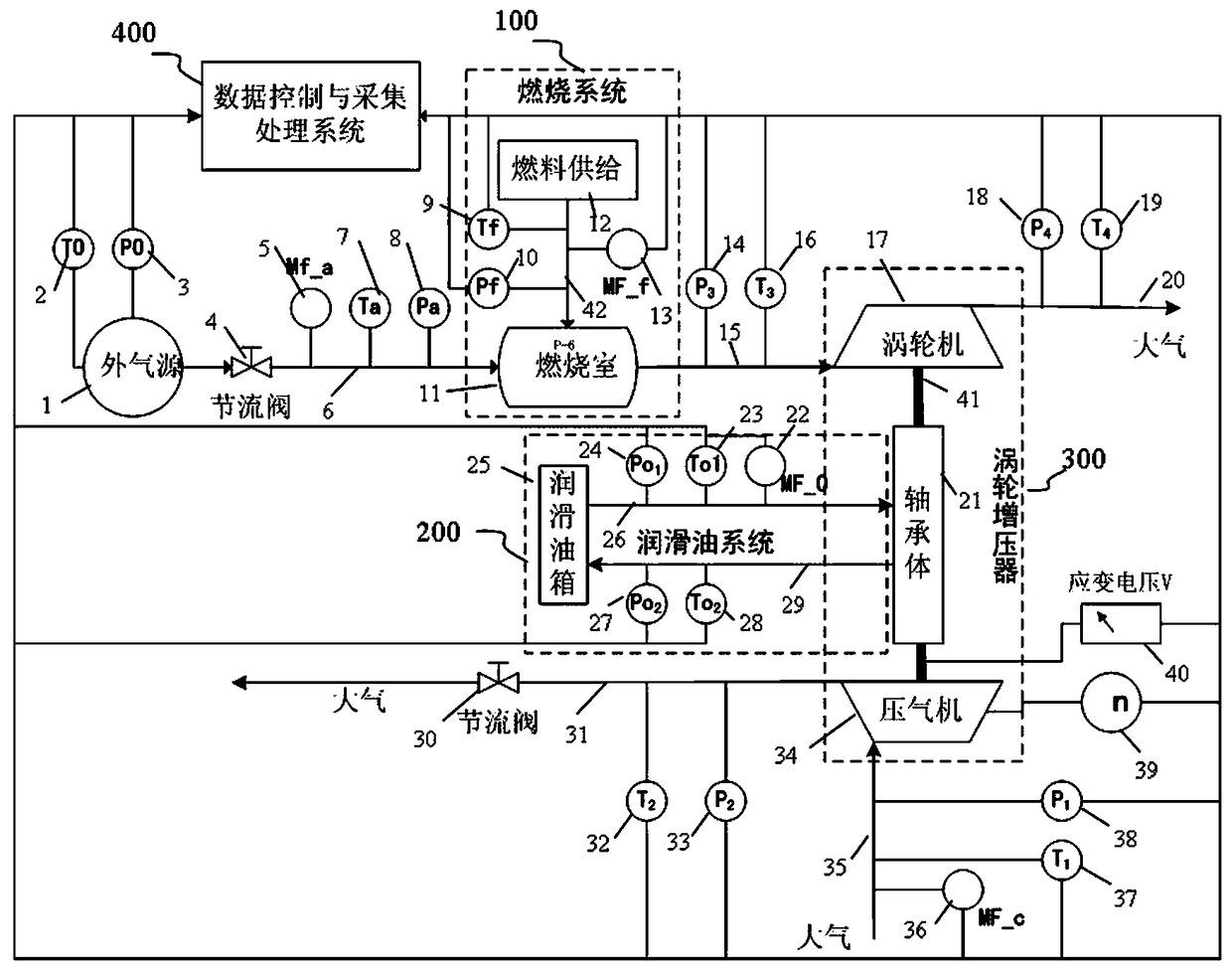
[0054] The detailed device of a turbocharger axial force measurement system of the present invention is as follows: figure 2 As shown, it includes an external air source 1, a combustion system 100, a lubricating oil system 200, a turbocharger 300, a data control and acquisition processing system 400, peripheral pipeline auxiliary systems and sensors.

[0055] The external air source 1 provides compressed air to enter the combustion chamber 11 through the combustion chamber intake pipeline 6, and the fuel supply system 12 in the combustion system 100 provides a corresponding proportion of fuel, which is fully mixed with the compressed air in the combustion chamber 11 to provide The gas that provides the required energy to the turbocharger 300 makes the working state of the turbocharger 300 conform to the actual working state of the tu...


PUM


Abstract

The invention provides an axial force measuring system for a turbocharger. The system comprises a combustion system, a lubricating oil system, a data control and acquisition processing system, an external pipeline auxiliary system, and sensors. The combustion system includes a fuel supply system and a combustion chamber connected with an external gas source. The lubricating oil system includes a lubricating oil box connected with a turbocharger by a pipeline. The sensors that are arranged inside a work device on a pipeline separated by the work device inside the turbocharger consists of a pressure sensor, a temperature sensor, a flow sensor, a rotating speed sensor, and strain gauge sensor. The external pipeline auxiliary system enables a gas circuit and an oil circuit to be connected. The data control and acquisition processing system is used for collecting sensor data and processing and outputting the data. In addition, the invention also relates a testing method. An all-condition condition can be simulated for testing; and testing not only can be realized on the measuring system but also can be realized on an engine. The system and method have advantages of good visual effect and high accuracy and sensitivity.

Description

technical field [0001] The invention belongs to the technical field of turbocharging, and in particular relates to a turbocharger axial force measuring system; the invention also relates to a testing method of the measuring system. Background technique [0002] The turbocharger is a typical rotating machine. The two ends of the same rotating shaft are connected to the turbine and the impeller. The turbine uses the energy of the exhaust gas discharged by the engine to expand and do work, and drives the impeller to compress more fresh air to provide the engine, improving engine power and economy. . When the blades of the turbine and impeller are rotating, axial force will be generated due to the action of gas, and the axial force will directly act on the thrust bearing of the turbocharger, which will affect the life of the thrust bearing and the operation of the turbocharger. Running stability as well as mechanical wear and tear can have adverse effects. In the process of pr...

Claims


Application Information

Patent Timeline
Patent Type & Authority Patents(China)
IPC IPC(8): G01L5/00
CPCG01L5/0061
Inventor 李亚静毕金光王志宏王保林蒋华锋许成罗翔亮孙杰
Owner NINGBO WEIFU TIANLI TURBOCHARGING TECH
Why Eureka
Try Eureka