Digital micromirror-based large dynamic laser far-field focal spot measurement system and measurement method

A digital micromirror and far-field focal spot technology, applied in the field of optics, can solve problems such as inapplicability to irregular focal spot measurement and cumbersome debugging work, so as to realize automatic monitoring and adjustment, improve stability and flexibility, and reduce debugging The effect of the process

Active Publication Date: 2016-12-21
XI'AN INST OF OPTICS & FINE MECHANICS - CHINESE ACAD OF SCI
View PDF5 Cites 6 Cited by
  • Summary
  • Abstract
  • Description
  • Claims
  • Application Information

AI Technical Summary

Problems solved by technology

[0003] In order to solve the technical problem that the traditional small ball occlusion dynamic range splicing method is cumbersome to debug and cannot be used for irregular focal spot measurement, the present invention provides a large dynamic laser far-field focal spot measurement system and measurement method based on digital micromirrors

Method used


Image

  • Digital micromirror-based large dynamic laser far-field focal spot measurement system and measurement method
  • Digital micromirror-based large dynamic laser far-field focal spot measurement system and measurement method

Examples


Embodiment Construction

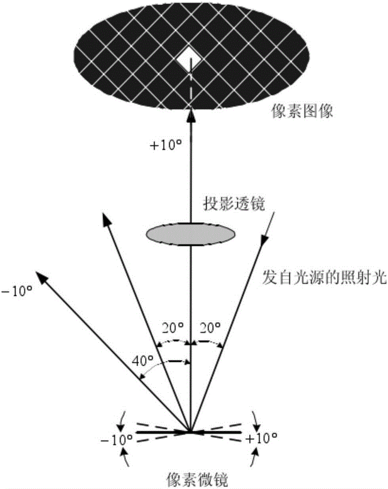
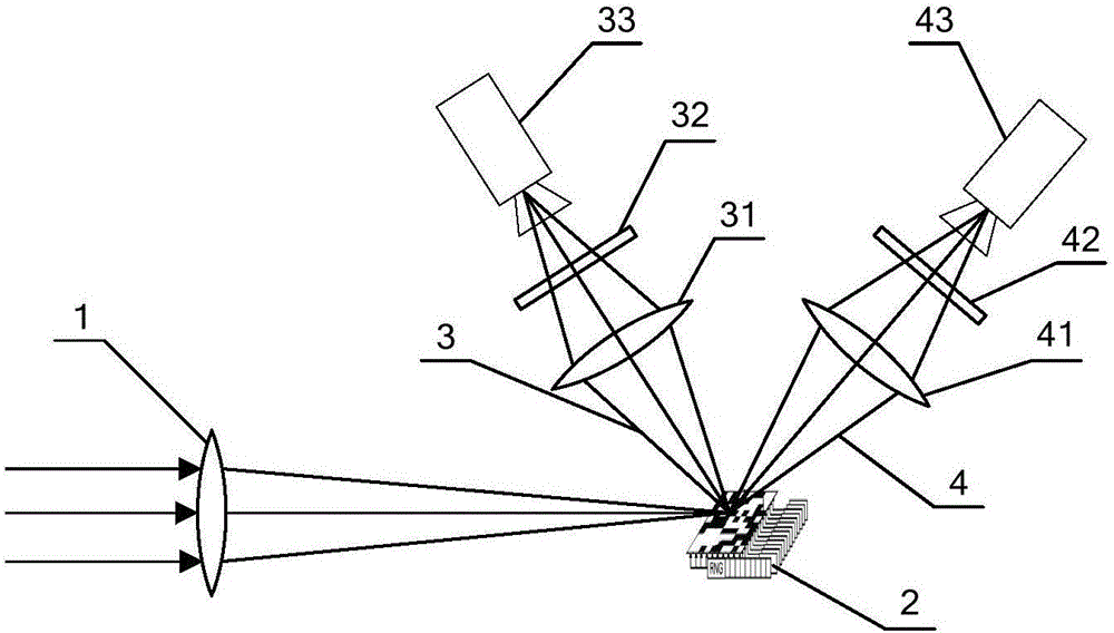
[0020] DMD digital micromirror is a chip-level beam control device produced by TI company in the United States. It controls the beam by controlling the flip state of the micromirror. DMD has been widely used in digital projection, compressed sensing and other fields. The far-field focal spot is imaged to the DMD mirror through the imaging system, and the flipping state of the micro-mirror is controlled by coding, so that the main lobe light path is reflected to one path, and the side lobe light path is reflected to the other path, and the focal spot information of the two paths is captured by two CCD cameras respectively. Receive to obtain the main lobe and side lobe focal spot images, and stitch the two images to obtain a high dynamic far-field focal spot image. Compared with the occlusion ball, through the software control of the flip posture of each micro-mirror of the DMD, the DMD can make corresponding adjustments for the drift of the focal spot position and the specific ...


PUM


Abstract

The invention belongs to the field of optics, and relates to a large dynamic far-field focal spot measurement device of a high energy laser system, particularly a digital micromirror-based large dynamic laser far-field focal spot measurement system and a measurement method thereof. The system comprises a focusing lens and a DMD digital micromirror. A light beam passing through the focusing lens is reflected by the DMD digital micromirror to generate a main-lobe light path and a side-lobe light path. A main-lobe imaging lens, a main-lobe attenuation slice and a main-lobe CCD detector are sequentially arranged in the light direction of the main-lobe light path. A side-lobe imaging lens, a side-lobe attenuation slice and a side-lobe CCD detector are sequentially arranged in the light direction of the side-lobe light path. According to the technical scheme of the invention, a DMD device is adopted to separate the main lobe and the side lobe of a far-field focal spot, so that the measurement system can be adjusted adaptively for different focal spot conditions. Therefore, the usage of a shielding ball is avoided, so that the stability and the flexibility of the measurement system can be greatly improved. Meanwhile, the debugging process can be effectively reduced, and the debugging difficulty is lowered. The debugging time is saved. The automatic monitoring and the automatic adjustment of far-field focal spots are achieved.

Description

technical field [0001] The invention belongs to the field of optics, and relates to a large dynamic far-field focal spot measurement device for a high-energy laser system, in particular to a large dynamic laser far-field focal spot measurement system and a measurement method based on a digital micromirror. Background technique [0002] With the maturity of laser technology, more and more large-scale, complex and high-energy laser systems have emerged in the field of optics. The far-field focal spot shape of a high-energy laser system is an important parameter for evaluating the beam quality of a laser system. Especially when it is used in the laser targeting process, the higher the energy concentration of the focal spot is required, the better, that is, the energy of the "side lobe" should be minimized, so The laser far-field focal spot is required to have a certain dynamic range, for example, the dynamic range of the laser focal spot used for inertial confinement fusion is ...

Claims


Application Information

Patent Timeline
Patent Type & Authority Applications(China)
IPC IPC(8): G01M11/02
CPCG01M11/0242
Inventor 袁索超李红光达争尚
Owner XI'AN INST OF OPTICS & FINE MECHANICS - CHINESE ACAD OF SCI
Why Eureka
Try Eureka