
Pipe cutting device

A cutting device and pipe material technology, applied in the direction of pipe shearing device, shearing device, positioning device, etc., can solve problems such as noise, affecting the physical and mental health of staff, and poor precision

Inactive Publication Date: 2017-01-04
WUHU CHENGDELONG FILTER EQUIP CO LTD
View PDF8 Cites 5 Cited by
  • Summary
  • Abstract
  • Description
  • Claims
  • Application Information

AI Technical Summary

Problems solved by technology

[0004] In view of the above-mentioned prior art, the purpose of the present invention is to overcome the problem that the noise reduction pipe cutting machine in the prior art only cuts the pipe, but the cutting accuracy is poor, and when a certain length of pipe needs to be cut, it is necessary to use a measuring tool for measurement , the operation is cumbersome, and the work efficiency is low; and in the cutting process, a lot of noise will be generated, the surrounding environment will be polluted, and the physical and mental health of the staff will be affected, so as to provide a method that can accurately cut different lengths during use, Simple and effective fixing, convenient operation, high work efficiency, and can effectively absorb and reduce the noise generated, thereby purifying the working environment and protecting the physical and mental health of the staff.

Method used


Image

  • Pipe cutting device
  • Pipe cutting device

Examples


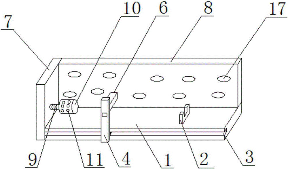
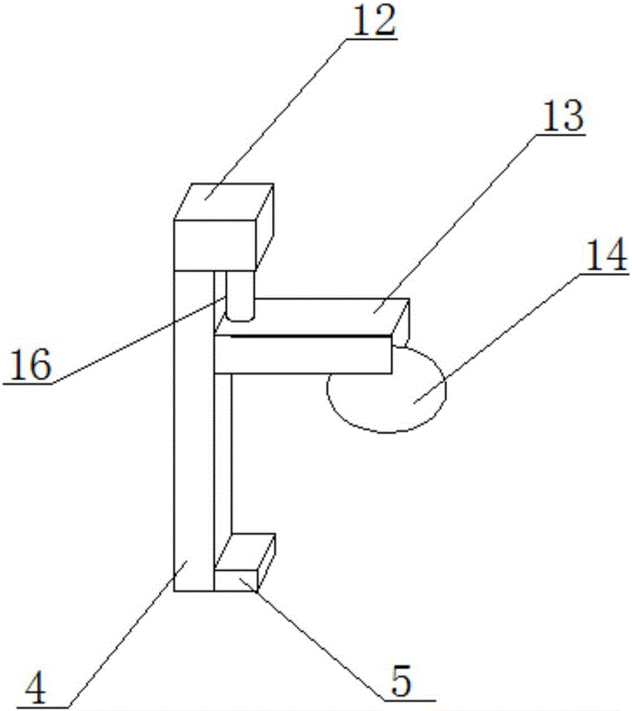
Embodiment Construction

[0025] Specific embodiments of the present invention will be described in detail below in conjunction with the accompanying drawings. It should be understood that the specific embodiments described here are only used to illustrate and explain the present invention, not to limit the present invention.

[0026] In the present invention, in the absence of a contrary description, the orientation words such as "upper, lower" and the like included in the term only represent the orientation of the term in the normal use state, or the common name understood by those skilled in the art, and should not be viewed as a limitation of this term.

[0027] The invention provides a pipe cutting device, which includes: a base 1, a baffle 7, a fixed column 10, a support column 4, a cutting device 6 and a sound insulation board 8, the base 1 is a cuboid, and the baffle The plate 7 is vertically arranged on the side of the base 1, and the fixed column 10 is fixed on the side of the baffle plate 7...


PUM


Abstract

The invention discloses a pipe cutting device. The pipe cutting device comprises a base, a retaining plate, a fixing column, a support column, a cutting device and a sound isolation plate, wherein the base is of a rectangle shape; the retaining plate is vertically arranged on the side surface of the base; the fixing column is fixedly arranged on the side surface, facing the upper surface of the base, of the retaining plate through a thread rod; one side surface, adjacent with the retaining plate, of the base is inwards depressed to form a slide groove; a slide block is fixedly arranged on the support column; the slide block is clamped into the slide groove, and can be slide along the length direction of the slide groove; the sound isolation plate is fixedly arranged on the other side surface, adjacent with the retaining plate, of the base, and is crossed with the retaining plate; the cutting device is arranged on the side surface, facing the base, of the support column, and can be slide along the length direction of the support column; the upper surface of the base is provided with scales which are matched with the cutting device. The pipe cutting device has the advantages that the problems of single function, poor cutting accuracy, complicated operation and low working efficiency of the denoising pipe cutting machine of the prior art are solved; the problems of noise production and pollution to surrounding environment in the cutting process are solved.

Description

technical field [0001] The present invention relates to a pipe cutting device. Background technique [0002] In the production process of pipes, cutting is a common process. Usually, noise-reducing pipe cutting machines are used to process pipes. However, the noise-reducing pipe cutting machines in the prior art only cut pipes, but the cutting accuracy is poor. When it is necessary to cut a certain length of pipe, it is necessary to measure it with a measuring tool, which is cumbersome and inefficient; moreover, a lot of noise will be generated during the cutting process, which will pollute the surrounding environment and affect the physical and mental health of the staff. [0003] Therefore, it is necessary to provide a device that can accurately cut different lengths during use, is simple and effective to fix, is convenient to operate, and has high work efficiency, and can effectively absorb and reduce the noise generated, thereby purifying the working environment and prot...

Claims


Application Information

Patent Timeline
IPC IPC(8): B23D21/00B23Q3/00B23Q11/00B23Q11/08
CPCB23D21/00B23Q3/00B23Q11/0096B23Q11/08B23Q2703/10
Inventor 胡德华
Owner WUHU CHENGDELONG FILTER EQUIP CO LTD
Learn More