Shearing stroke control method for plate shearing machine based on plate width

A control method and shearing machine technology, applied in the direction of program control, computer control, shearing machine control device, etc., can solve the problems of affecting shearing efficiency, shearing accuracy cannot be guaranteed, and increase maintenance cost of machine tool manufacturers

Active Publication Date: 2017-01-04
NANJING ESTUN AUTOMATION CO LTD
View PDF5 Cites 0 Cited by
  • Summary
  • Abstract
  • Description
  • Claims
  • Application Information

AI Technical Summary

Problems solved by technology

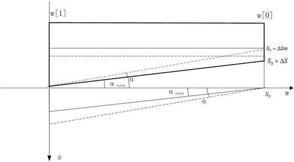
This control method has certain limitations, because the potentiometer can only feed back the stroke of the tool post in the vertical direction. If the shear angle of the tool post changes, the system will not automatically adjust the corresponding relationship between the width of the sheet and the feedback value of the potentiometer. , so the cutting accuracy cannot be guaranteed. When cutting a sheet with the same width, it may not be completely cut or the sheet will go down a long distance after cutting the sheet. In order to ensure the cutting accuracy, the user needs to calibrate the sheet width again. The corresponding relationship with the feedback value of the potentiometer, this method seriously affects the shearing efficiency, and also increases the maintenance cost of the machine tool manufacturer in the later period
[0007] At present, the research in the industry on the shear distance is mainly based on the upper and lower limit switch control and time relay control, and the potentiometer control is rarely used, mainly because the control accuracy of the board width cannot meet the user's requirements.

Method used


Image

  • Shearing stroke control method for plate shearing machine based on plate width
  • Shearing stroke control method for plate shearing machine based on plate width
  • Shearing stroke control method for plate shearing machine based on plate width

Examples


Embodiment Construction

[0085] The method of the present invention will be further described in detail below in conjunction with the embodiments and accompanying drawings.

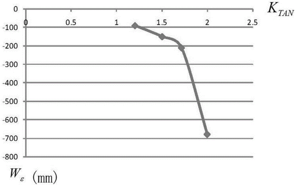
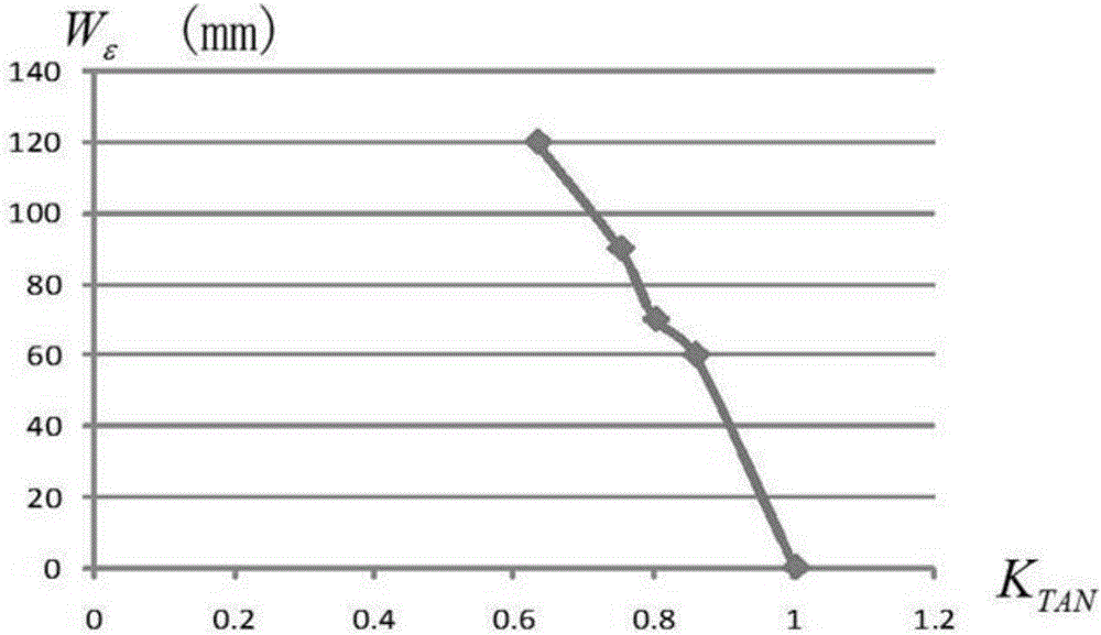
[0086] First determine the maximum shear angle and minimum shear angle of the machine tool, set the shear angle range to 0.5°-2.0°, and select the calibration angle α norm = 1.2°.

[0087] It is known that the maximum shear distance of the machine tool is 3200mm. Adjust the shearing angle of the knife post to 1.2°, perform the shearing action, and record the feedback voltage value when the shearing plate width is 0mm and the feedback voltage value when the shearing plate width is 3200mm. Enter the data into the shear voltage parameter table, as shown in Table 2.

[0088] Table 2 Parameter table under calibration angle

[0089] Shear plate width(mm) Voltage value (V) 3200 4 0 8

[0090] Set target clipboard width W target It is 2000mm, and the shearing action is performed. After measurement, it is fo...


PUM


Abstract

The invention discloses a shearing stroke control method for a plate shearing machine based on the plate width. A potentiometer is used for collecting voltage, and the shearing stroke of a tool rest in the vertical direction is mapped into the shearing plate width in the horizontal direction. At any shearing angle, the current shearing plate width can be deduced through voltage feedback of the potentiometer. The beforehand stopping shearing plate width is set for offsetting the influence of the motion inertia of the tool rest on the shearing stroke control. After the plate shearing machine is corrected through the algorithm in the method, at any shearing angle, the shearing plate width error can reach the shearing precision the same as the error under the calibrated shearing angle, the using requirement of a user is met, the error range is a positive value, and it is ensured that due to the too short shearing stroke, plates are scraped cannot happen. Meanwhile, the shearing efficiency is improved, energy consumption is reduced, and due to the fact that the user does not need to conduct repeated calibration on the shearing plate width or angle, usage is facilitated for the user, and the work efficiency is improved.

Description

technical field [0001] The invention relates to a method for controlling the shear distance of a plate shearing machine, in particular to a method for controlling the shear distance of a plate shearing machine based on plate width. Background technique [0002] With the help of the moving upper blade and the fixed lower blade, the shearing machine shears, fractures and separates the board according to the required size of the board. Shearing machine is often used to cut the sheet blank with straight edge. It is mainly used in metal processing industry and belongs to a kind of forging machinery. If the shearing process is too short, the plate will be scrapped due to incomplete shearing; if the shearing process is too long, the work efficiency will be reduced and energy consumption will be increased. Therefore, precise control of the shear distance is very necessary. [0003] At present, the shear range control of the shearing machine mainly includes three methods: upper and...

Claims


Application Information

Patent Timeline
Patent Type & Authority Applications(China)
IPC IPC(8): B23D36/00G05B19/404
CPCB23D36/00G05B19/404Y02P70/10
Inventor 宋春桃徐林飞吴波
Owner NANJING ESTUN AUTOMATION CO LTD
Why Eureka
Try Eureka