Detecting device and method for machining

A detection device and machining technology, applied in the field of detection, can solve the problems of vibration deviation, signal interference, can not be found in time, and the environmental impact of the dial indicator fluctuates greatly, so as to achieve the effect of sensitive displacement.

Inactive Publication Date: 2017-01-04
HIMILE MECHANICAL MFG
View PDF5 Cites 7 Cited by
  • Summary
  • Abstract
  • Description
  • Claims
  • Application Information

AI Technical Summary

Problems solved by technology

This method relies too much on manpower, and once the workpiece moves, it cannot be detected and taken measures in time, and because the dial indicator itself is greatly fluctuated by the environment, especially in wet and watery places, it needs to be replaced frequently Measuring tools; and in the compact CNC machine tool processing room, the installation and adjustment of the dial indicator is very inconvenient
[0004] With the rise of sensor technology, this technology has also been introduced into machine tools at present, but the sensor is affected by working conditions and the environment, vibration deviation, signal interference, etc. are difficult to solve, and static measurement cannot meet today’s processing needs. Adding sensors to meet dynamic measurement may be expensive, so a device that can adapt to various complex environments, does not need to be integrated with the machine tool, is easy to install and can realize real-time detection

Method used


Image

  • Detecting device and method for machining
  • Detecting device and method for machining
  • Detecting device and method for machining

Examples


Embodiment 1

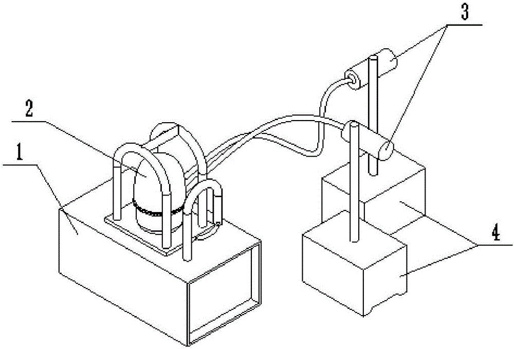
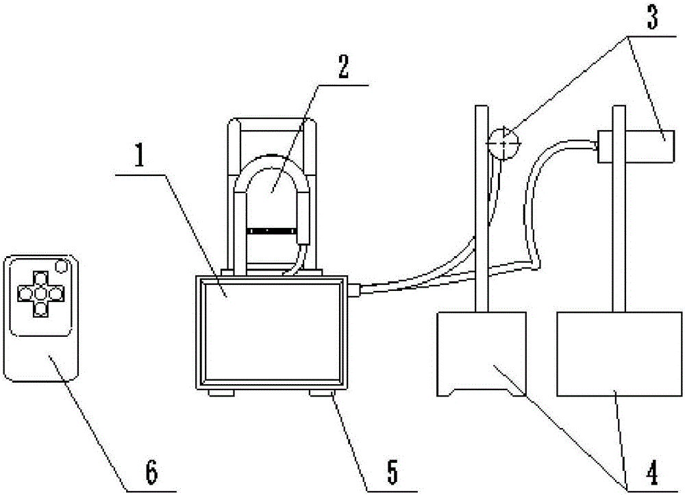
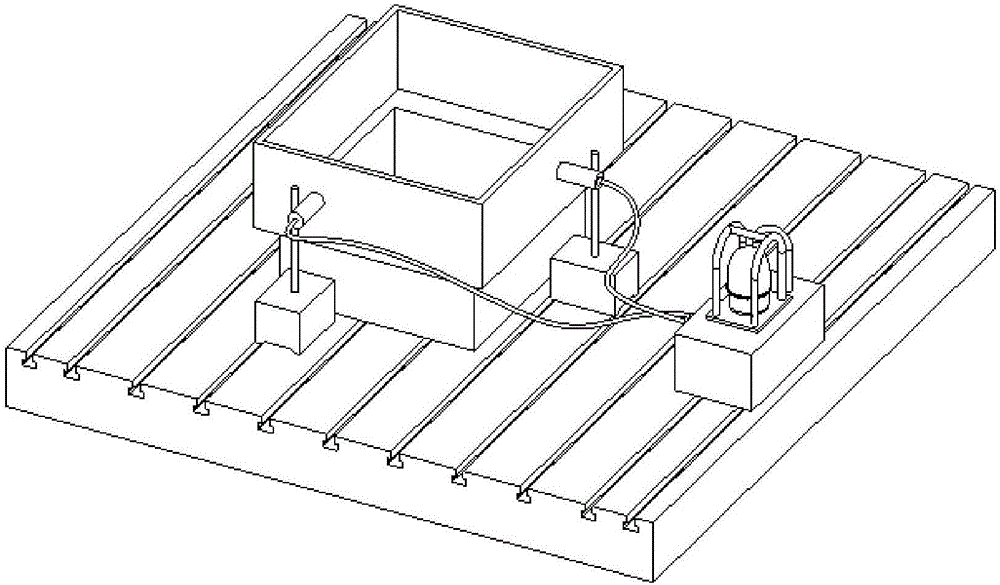
[0048] Place the detection device on the worktable of the CNC machine tool. The magnet 5 at the bottom of the controller 1 firmly connects the housing of the controller 1 with the worktable; the magnetic meter base 4 is attached to the worktable of the machine tool to make the measuring probe 3 Point to the surface of the workpiece to be measured, such as image 3 As shown, there are two measuring probes 3, which are used to detect the movement of the workpiece surface in X and Y directions respectively, and then move the measuring probe 3 so that the value displayed on the display 7 on the controller 1 is close to 2.00 mm. At this time, the remote control 6 is used to adjust the deviation alarm value of the workpiece to be measured in the controller 1, and then the measurement is started. The CNC machine tool starts processing. Once the movement of the workpiece to be measured exceeds the alarm setting value, the controller 1 will control the alarm device 2 to send out an alarm...

Embodiment 2

[0050] The same parts as in the first embodiment will not be repeated. The measuring probe 3 is provided with a wireless transmitting device 8. The measuring probe 3 detects the position offset of the workpiece to be measured and outputs an electrical signal corresponding to the position offset through the wireless transmitting device 8 Output a wireless signal corresponding to the position offset and receive it by the controller 1. The controller 1 controls the alarm device 2 to give an alarm, or directly feeds the signal to the overall control system of the machine tool to control the machine tool to alarm or stop working .


PUM


Abstract

The invention discloses a detecting device and method for machining and belongs to the field of detection. The detecting device for machining comprises measuring probes and a control circuit. The measuring probes are arranged on supports of magnetic force gauge stands. The measuring probes are pointed to the surface of a workpiece to be detected. The control circuit comprises a controller and an alarming device. The controller is in signal connection with the measuring probes. The measuring probes convert collected information and send the converted information to the controller. The alarming value of deviation of the workpiece to be detected is stored in the controller. The controller is also connected with an indication device. The detecting device can detect the movement condition of the workpiece in real time in the machining process of a machine tool, and the problem that in the prior art, detection only depends on regular checking conducted by operation personnel, so that the real-time performance is low is effectively solved.

Description

Technical field [0001] The invention relates to the field of detection, in particular to a detection device and a detection method for mechanical processing. Background technique [0002] CNC machining liberated a lot of labor, but because people trust the machine too much, in the actual machining process of the CNC machine tool, after people input the information, they leave the machine tool to deal with other machine tools or things. However, when the CNC machine tool is processing the workpiece, if it appears If the tooling is not fully locked, the fixing method is incorrect, the cutting amount is too large, etc., it may cause the workpiece to shift during the processing. If this kind of deviation cannot be detected and processed in time, it will cause misprocessing or even scrapping of the workpiece to be tested, resulting in huge economic losses. [0003] In order to prevent the workpiece from moving during the machining of the machine tool, the existing method is to support ...

Claims


Application Information

Patent Timeline
IPC IPC(8): B23Q17/22
CPCB23Q17/22
Inventor 吴庆龙程旭波
Owner HIMILE MECHANICAL MFG
Why Eureka
Try Eureka