Multi-station rotary forming machine

A molding machine and multi-station technology, applied in the fields of injection blowing or injection stretch blowing plastic bottle manufacturing equipment and multi-station rotary molding machines, can solve the problems of unstable up and down operation, complicated mechanism setting, complicated working process, etc. Achieve the effect of saving energy consumption, increasing the mold layout space, and saving cycle time

Inactive Publication Date: 2017-01-04
柳州市精业机器有限公司
View PDF6 Cites 2 Cited by
  • Summary
  • Abstract
  • Description
  • Claims
  • Application Information

AI Technical Summary

Problems solved by technology

The invention patent with the patent number ZL 200910305311.8 discloses a double-station reciprocating rotary injection-stretch blow molding machine, see the patent figure 1 As shown, the injection mandrel 23 is connected to the piston rod 211 of the core-pulling cylinder 21 through the base 22, and the core-pulling cylinder is installed on the upper template corresponding to the injection module above, and also plays a role of mold locking during injection. Therefore, the diameter of the core-pulling cylinder is almost the same as that of the clamping cylinder. This structure is relatively unstable when running up and down, and consumes a lot of energy. In addition, the molding machine includes not only the core-pulling cylinder and the clamping cylinder, but also Multiple cylinder structures such as sealing cylinder, stretching cylinder and two clamping cylinders, the mechanism settings are complicated, the working process is complicated, and the efficiency is low

Method used


Image

  • Multi-station rotary forming machine
  • Multi-station rotary forming machine
  • Multi-station rotary forming machine

Examples


Embodiment Construction

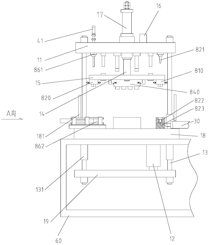
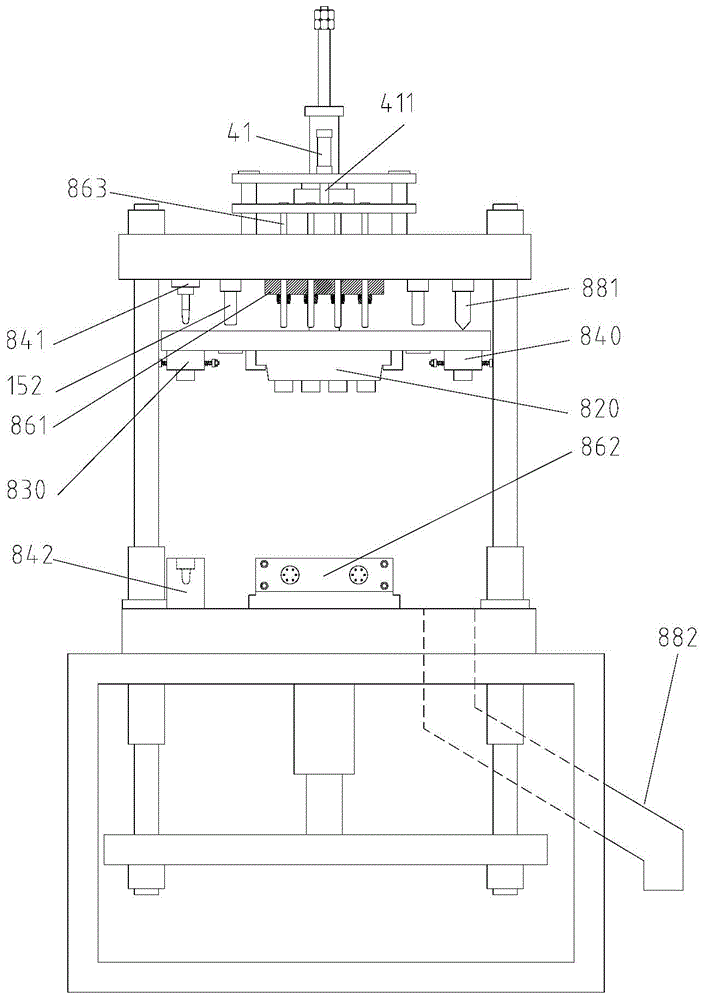
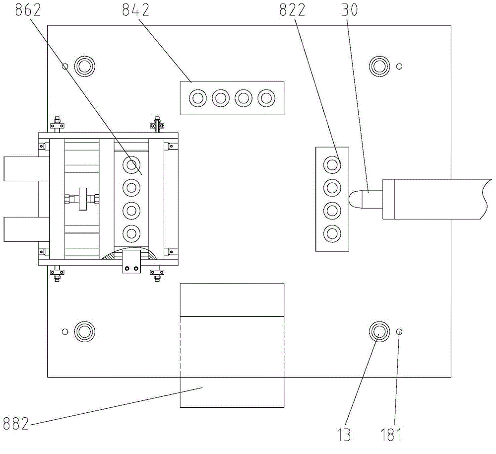
[0026] figure 1 It is a schematic diagram of the overall structure of the present invention; figure 2 for figure 1 A-direction view; image 3 for figure 1 top view. Such as figure 1 , figure 2 and combine image 3 As shown, the present invention provides a multi-station rotary molding machine, which includes a main machine and different working modules arranged on the main machine. Described main engine comprises frame 60, and workbench panel 18 is horizontally fixed on the frame 60, and workbench panel 18 is connected with lower formwork 19 through clamping oil cylinder 12, and lower formwork 19 passes through the guide column of workbench panel 18 vertically. 13 is connected with the upper template 11, and the upper template 11 is provided with a push-down oil cylinder 17. Figure 4 It is a schematic diagram of the local structure of the push-down oil cylinder, the upper template and the rotating disk of the present invention. Such as Figure 4 As shown, the push...


PUM


Abstract

The invention provides a multi-station rotary forming machine. The multi-station rotary forming machine comprises a main machine as well as an injection mold set and a stretch blow molding mold set which are arranged on the main machine. The main machine comprises a rack (60). A workbench panel (18) is fixed to the rack and connected with a lower mold plate (19) through a mold locking oil cylinder (12). The lower mold plate is connected with an upper mold plate (11) through a guide column (13). A rotary disk (15) is arranged below the upper mold plate and connected with a rotary driving mechanism (16). The injection mold set mainly comprises an injection opening mold set (810), a core mold set (821) and a female mold set (822). The injection opening mold set is fixedly arranged on the lower surface of the rotary disk and corresponds to the core mold set and the female mold set in position. The core mold set is directly and fixedly arranged on the lower end surface of the upper mold plate. A downward pushing oil cylinder (17) is arranged above the upper mold plate. A piston rod (171) of the downward pushing oil cylinder is connected with the rotary disk (15). According to the multi-station rotary forming machine, the structure is simplified and reasonable, operation action is stable, energy consumption is reduced, the requirements for the diversity of products are met, and the production efficiency is high.

Description

technical field [0001] The invention relates to an injection-blow or injection-stretch-blow plastic bottle manufacturing equipment, in particular to a multi-station rotary molding machine, which belongs to the technical field of mechanical manufacturing. Background technique [0002] Blow molding is the third largest plastic molding method after injection molding and extrusion molding, and it is also the fastest growing plastic molding method. The invention patent with the patent number ZL 200910305311.8 discloses a double-station reciprocating rotary injection-stretch blow molding machine, see the patent figure 1 As shown, the injection mandrel 23 is connected to the piston rod 211 of the core-pulling cylinder 21 through the base 22, and the core-pulling cylinder is installed on the upper template corresponding to the injection module above, and also plays a role of mold locking during injection. Therefore, the diameter of the core-pulling cylinder is almost the same as th...

Claims


Application Information

Patent Timeline
Patent Type & Authority Applications(China)
IPC IPC(8): B29C49/06B29C45/26B29C49/70B29C49/78B29C49/48B29C45/78
Inventor 文澜李晖梁家炳肖彩飞姚林平
Owner 柳州市精业机器有限公司
Why Eureka
Try Eureka