One sheath double-core microfluidic control nozzle, spinning device and spinning method

A technology of microfluidics and nozzles, which is applied in the field of nanomaterials, can solve problems such as complex nanofiber technology, and achieve significant technological progress, prevent splitting, and simple application

Inactive Publication Date: 2018-12-14
UNIV OF SHANGHAI FOR SCI & TECH
View PDF8 Cites 0 Cited by
  • Summary
  • Abstract
  • Description
  • Claims
  • Application Information

AI Technical Summary

Problems solved by technology

[0005] Aiming at the above-mentioned technical problems in the prior art, the present invention provides a one-sheath dual-core microfluidic control nozzle, a spinning device and a spinning method. The one-sheath dual-core microfluidic control nozzle and spinning device And the spinning method will solve the complex technical problem of preparing nanofibers with complex structural characteristics of a sheath and double cores in the prior art

Method used


Image

  • One sheath double-core microfluidic control nozzle, spinning device and spinning method
  • One sheath double-core microfluidic control nozzle, spinning device and spinning method
  • One sheath double-core microfluidic control nozzle, spinning device and spinning method

Examples


Embodiment 1

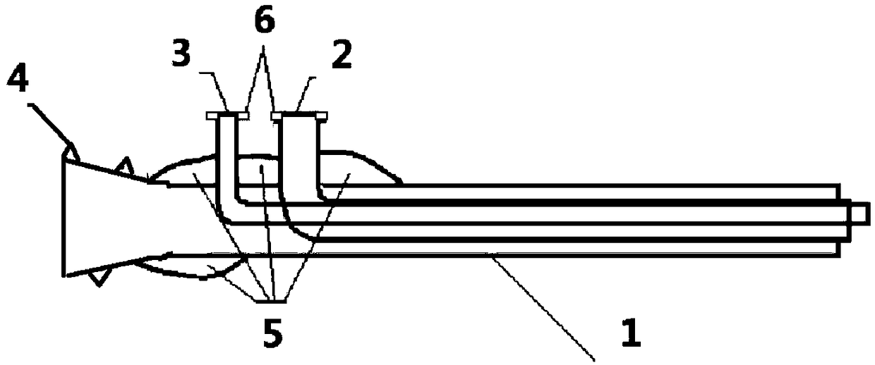
[0030] A sheath double-core microfluidic control nozzle, its structure schematic diagram is as follows figure 1As shown, it includes a total capillary 1, a first curved capillary 2 and a second curved capillary 3; the outer diameter of the first curved capillary 2 is smaller than the inner diameter of the total capillary 1, and the second curved capillary 3 The outer diameter of the first curved capillary 2 is smaller than the inner diameter of the first curved capillary 2, and the first curved capillary 2 is arranged in the total capillary 1, and the curved end of the first curved capillary 2 is connected from the total The side wall of the inlet end of the capillary 1 passes through, and the other end of the first curved capillary 2 passes through the center of the outlet end of the total capillary 1; the straight section of the second curved capillary 3 is arranged on the In the first curved capillary 2 described above, one end of the second curved capillary 3 passes throug...

Embodiment 2

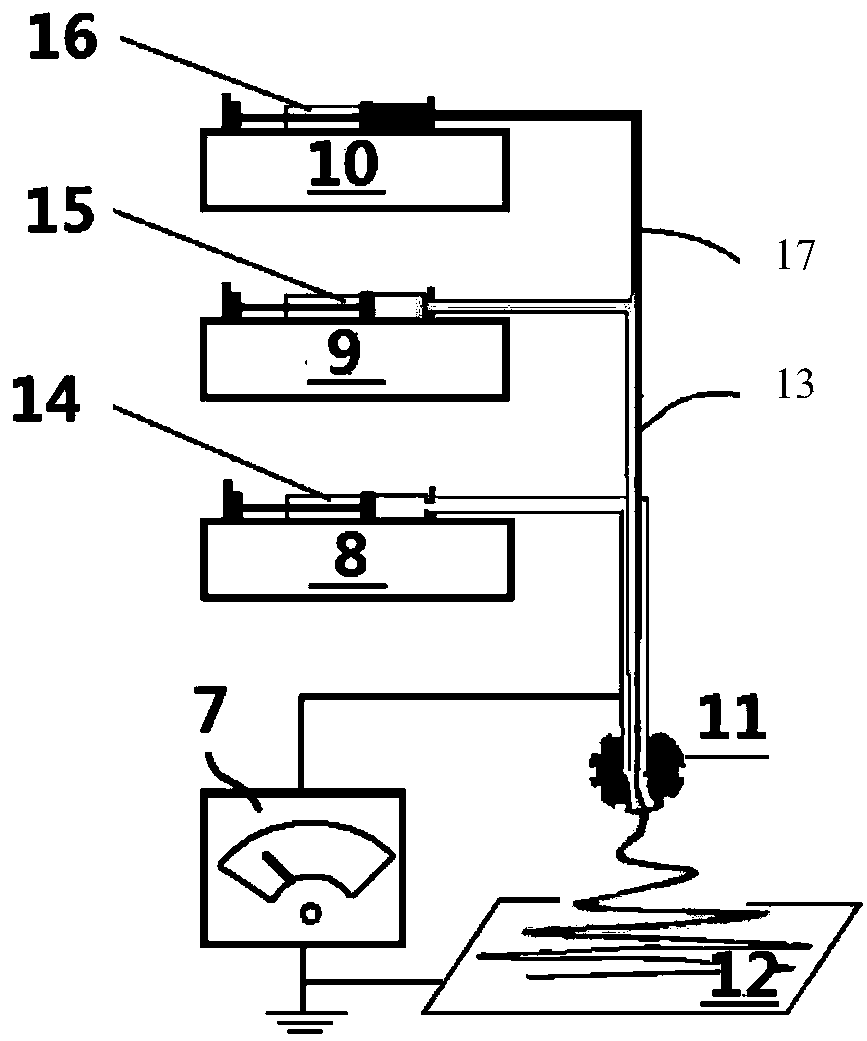
[0035] A high-voltage electrospinning device assembled using the nozzle, its composition schematic diagram is as follows image 3 As shown, it includes a high-pressure generator 7, a first syringe pump 8, a second syringe pump 9, a third syringe pump 10, a sheath dual-core microfluidic control nozzle 11, a fiber receiving plate 12, and a first high-elastic silicone hose 17 , the first syringe 14, the second syringe 15, the third syringe 16, and the second high elastic silicone hose 13.

[0036] The electrospinning device with a sheath dual-core microfluidic control nozzle is used to perform electrospinning on the three fluids. The specific steps are as follows: the first syringe 14 is installed in the first syringe pump 8, and the first outer sheath spinning is added to the syringe 14. silk liquid, the first syringe 14 is directly connected to the interface of a sheath dual-core microfluidic control nozzle 11 . The second syringe 15 is installed in the second syringe pump 6, ...


PUM

PropertyMeasurementUnit
lengthaaaaaaaaaa
diameteraaaaaaaaaa

Abstract

The invention provides a one-sheath twin-core microfluid control sprayer which comprises a main capillary tube, a first bent capillary tube and a second bent capillary tube, wherein the first bent capillary tube is arranged in the main capillary tube; the bent end of the first bent capillary tube penetrates through the side wall of the inlet end of the main capillary tube, and the other end of the first bent capillary tube penetrates through center of the outlet end of the main capillary tube; a straight line section of the second bent capillary tube is arranged in the first bent capillary tube; the bent part of the second bent capillary tube penetrates through the side wall of the inlet end of the main capillary tube. The invention further provides a high-voltage electrostatic spinning device which comprises a first injection pump, a second injection pump, a third injection pump, a silica gel hose, a fiber receiving plate, a high-pressure generator and the one-sheath twin-core microfluid control sprayer. The invention further provides an implementation method for adopting the high-voltage electrostatic spinning device to prepare one-sheath twin-core structured nanofiber; the one-sheath twin-core structured nanofiber can be effectively prepared through a single step.

Description

technical field [0001] The invention belongs to the field of nanomaterials and relates to a spinning device, specifically a one-sheath double-core microfluidic control nozzle, a multi-fluid electrospinning device with a one-sheath double-core microfluidic control nozzle, and the use of The device is a single-step electrospinning method for preparing a sheath double-core structure nanofiber. Background technique [0002] High-voltage electrospinning technology, referred to as electrospinning, is a top-down nano-manufacturing technology. The jet is formed by overcoming the liquid surface tension and viscoelastic force of the droplets at the tip of the nozzle by applying an electric field force. Under the joint action of force and surface tension, the atomized liquid jet is bent, stretched, and split by high frequency, and it is stretched tens of millions of times in tens of milliseconds, and the nano-scale is obtained at the receiving end through solvent volatilization or melt...

Claims


Application Information

Patent Timeline
Patent Type & Authority Patents(China)
IPC IPC(8): D01D5/00
CPCD01D5/0015D01D5/0069
Inventor 余灯广李郝林郑招斌张曼
Owner UNIV OF SHANGHAI FOR SCI & TECH
Why Eureka
Try Eureka