Anchor rod assembly and anchorage device with same

A technology of bolts and components, which is applied in the direction of installation of bolts, sheet pile walls, mining equipment, etc., can solve problems such as high repair rate, damage of support structure, failure of bolt support, etc., and achieve maintenance safety and stability, control Deformation of surrounding rock and effect of enlarging the effective section

Inactive Publication Date: 2017-01-04
CHINA ENFI ENGINEERING CORPORATION
View PDF11 Cites 1 Cited by
  • Summary
  • Abstract
  • Description
  • Claims
  • Application Information

AI Technical Summary

Problems solved by technology

Under the condition of high ground stress, the deformation of the ordinary bolt structure cannot match the large deformation of the surrounding rock, and it is often broken due to insufficient elongation, and the bolt support fails, which will cause damage to the support structure and reduce the repair rate. High, waste a lot of manpower, material and financial resources, and cause heavy losses

Method used


Image

  • Anchor rod assembly and anchorage device with same
  • Anchor rod assembly and anchorage device with same
  • Anchor rod assembly and anchorage device with same

Examples


Embodiment 1

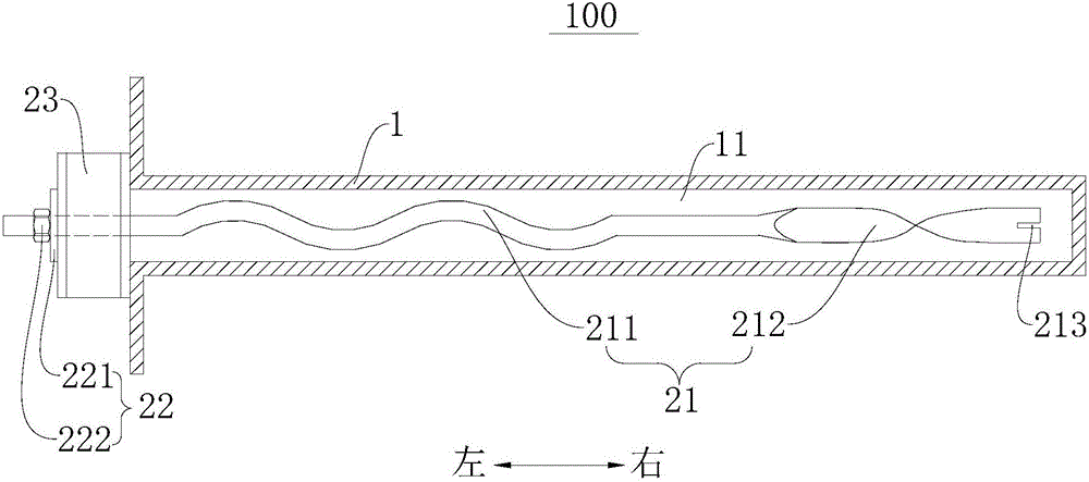
[0053] refer to figure 1 The anchoring device 100 includes a base body 1 and a bolt assembly 2, wherein the base body 1 may be surrounding rock, and an installation hole 11 is formed on the base body 1, and the installation hole 11 is filled with an anchoring agent.

[0054] The anchor rod assembly 2 includes an anchor rod 21 , a pressing member 23 and a limiting member 22 . Wherein, the anchor rod 21 extends along the left-right direction, and the anchor rod 21 includes a curved section 211 inserted into the installation hole 11 and a stirring section 212, the curved section 211 is corrugated extending along the left-right direction; the stirring section 212 is connected to the right end of the curved section 211 , and the stirring section 212 is in a flat shape extending from left to right. In the direction from left to right, the stirring section 212 is in a twist shape gradually twisting around the axis of the anchor rod 21. Further, the end face of the right end of the st...

Embodiment 2

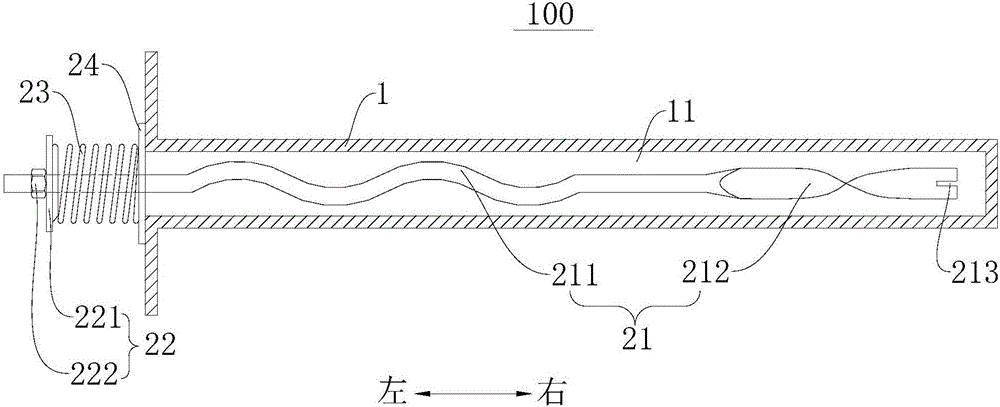
[0059] Such as figure 2 As shown, the structure of this embodiment is substantially the same as that of Embodiment 1, wherein the same components use the same reference numerals, the only difference is that: the anchor rod assembly 2 in Embodiment 1 only includes the anchor rod 21, pressure relief Part 23, position-limiting part 22, and allow pressure part 23 to be a steel pipe. However, the bolt assembly 2 described in the second embodiment includes a bolt 21, a pressing member 23, a limiting member 22 and a second backing plate 24, and the second backing plate 24 is placed between the pressing member 23 and the surrounding rock. And let the pressing member 23 be a spring, wherein the spring can be a cylindrical coil spring, a disc spring, a composite spring, or a bellows.

[0060] According to the anchoring device 100 of the embodiment of the present invention, the spring of the pressing member 23 can apply a certain prestress to the anchor rod 21 to realize active support...


PUM


Abstract

The invention discloses an anchor rod assembly and an anchorage device with the same. The anchor rod assembly comprises an anchor rod, a limiting piece and a yielding piece, wherein the anchor rod comprises a curved section suitable for being inserted in a base body, and the curved section is in a curved shape in the axis direction of the anchor rod; the limiting piece is connected with the anchor rod but spaced from the curved section; the yielding piece is arranged on the anchor rod and located on the side, facing the curved section, on the limiting piece; and the yielding piece is suitable for abutting against the base body and the limiting piece when the curved section of the anchor rod is inserted in the base body. according to the anchor rod assembly, through the yielding piece and the curved section arranged on the anchor rod, the deformation amount of the anchor rod assembly can be increased, yielding to a greater extent can be achieved, accordingly, surrounding rock deformation can be effectively controlled while the anchor rod is protected against tensile failure, the anchor rod and surrounding rock are used for bearing jointly, and safety and stability of an underground project are maintained. Besides, the exposure length of the anchor rod can be reduced, and the effective section of the underground project is enlarged.

Description

technical field [0001] The invention relates to the technical field of surrounding rock support, in particular to a bolt assembly and an anchor device with the same. Background technique [0002] With the development of transportation construction and the exploitation of resources into the deep, surrounding rock support under high ground stress has become one of the problems that must be faced in underground engineering. Under the condition of high ground stress, the deformation of the ordinary bolt structure cannot match the large deformation of the surrounding rock, and it is often broken due to insufficient elongation, and the bolt support fails, which will cause damage to the support structure and reduce the repair rate. High, waste a lot of manpower, material and financial resources, and cause heavy losses. Contents of the invention [0003] The present invention aims to solve at least one of the technical problems existing in the prior art. For this reason, the pre...

Claims


Application Information

Patent Timeline
IPC IPC(8): E21D21/00E02D5/74
CPCE21D21/0026E02D5/74
Inventor 郭相参安建英王建中崔传杰王鹏飞张晓龙
Owner CHINA ENFI ENGINEERING CORPORATION
Why Eureka
Try Eureka