Novel harmonic reducer and input transmission structure thereof

A technology of harmonic reducer and transmission structure, which is applied in the direction of transmission device, gear transmission device, belt/chain/gear, etc., which can solve the problem of the working life of the easily damaged harmonic reducer, the unstable operation of the reducer, and the large stress of bearing assembly and other problems to achieve the effect of eliminating stress in the working process, compact structure, and improving stability

Active Publication Date: 2017-01-04
HUNAN UNIV
View PDF6 Cites 20 Cited by
  • Summary
  • Abstract
  • Description
  • Claims
  • Application Information

AI Technical Summary

Problems solved by technology

When the bearing is placed on the cam, the cam stretches the bearing into an oval shape, which makes the assembly stress of the bearing very large, and the bearing, especially the inner ring of the bearing, is easily damaged during the rotation process, which shortens the working life of the harmonic reducer. Greatly reduced
In addition, since the flexspline needs to achieve power output, a certain output connection stiffness is required, and the deformation of the flexspline requires a certain degree of flexibility. Therefore, the existing flexspline is usually made of alloy metal, but its hardness is relatively high. Therefore, in order to alleviate the stress of the teeth between the flex spline and the steel wheel, the fit between the teeth is often set as a fit with clearance to reduce the stress during rotation, but this will easily cause the reducer to run unevenly

Method used


Image

  • Novel harmonic reducer and input transmission structure thereof
  • Novel harmonic reducer and input transmission structure thereof
  • Novel harmonic reducer and input transmission structure thereof

Examples


Embodiment 1

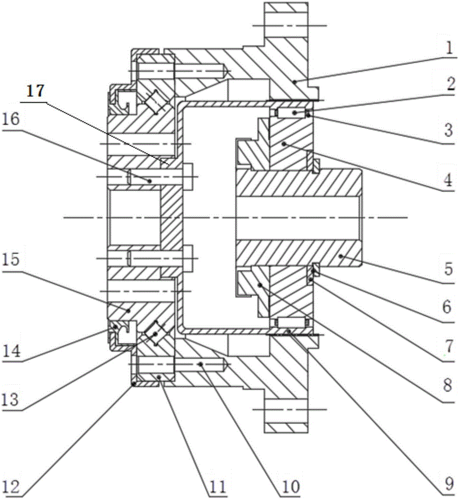
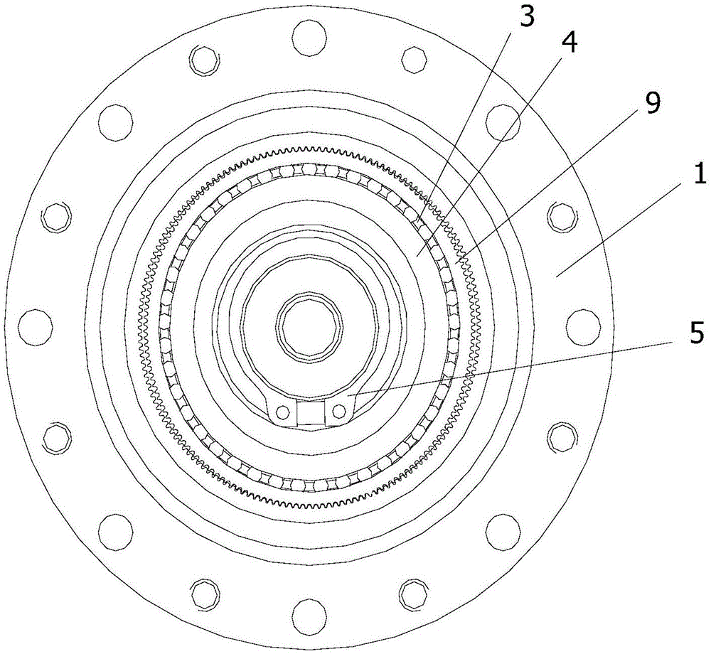
[0043] like figure 1 and figure 2 As shown, a new type of harmonic reducer input transmission structure, including the cam 4 connected to the input shaft, the cam 4 is covered with a flex spline 9; the flex spline 9 is externally meshed with a steel wheel 1; the flex spline 9 is provided with external teeth, The steel wheel 1 is provided with internal teeth, and the flex spline 9 and the steel wheel 1 are meshed through the external teeth and the internal teeth; a cage 3 is provided between the flex spline 9 and the cam 4, and cylindrical rollers 2 are installed in the cage 3; The inside of the wheel 9 and the outside of the cam 4 are both convexly formed with an annular convex circle 19, and a C-shaped groove 20 matching with the cylindrical roller 2 is formed on the annular convex circle 19; the annular convex circle 19 is located on the outer tooth side of the flexwheel 9 .

[0044] The present invention cancels the setting of the bearing by changing the structure of the...

Embodiment 2

[0046]The fatigue failure of the harmonic reducer mostly occurs in the flex spline and the bearing, so the meshing degree and mode of the flex spline and the steel wheel have a great influence on the stability and life of the harmonic reducer. In the present invention, the flexible spline is made of PA 12 plastic. Because its elasticity is better than the elastic metal used in the original flexspline manufacturing, the external teeth on the flexible spline that are opposite to the long axis of the cam can completely mesh with the internal teeth of the steel wheel. No backlash, if attached Figure 5 shown. Among them, the tooth profile curve is composed of R1, R2, R3 three-segment curves and R1', R2', R3' three-segment curves that are symmetrical to it, and the starting or adjacent curves of the curve intersect at P 1 ,P 2 ,P 3 ,P 4 (P 4 '), P 3 ',P 2 ',P 1 '. In Cartesian coordinates, the curve equations of R1, R2, and R3 are shown below. This design method can impro...

Embodiment 3

[0061] The PA 12 used in the flexible wheel of the harmonic reducer of the present invention is an engineering plastic with low specific gravity, high tensile strength, wear resistance, good self-lubrication, excellent impact toughness, and both rigidity and flexibility, rather than metal Material. Its elastic modulus is 1.646GPa, and its shrinkage rate can reach 1% to 2%. like figure 1 As shown, the harmonic reducer of the present invention is input into a traditional structure, and the cam 4 of the transmission structure is in the shape of an ellipse, and the contour curve satisfies the equation: r=0.5r B +ωcos(2θ), there is a C-shaped groove on the outer surface of the cam. The flexible spline 9 has an annular convex circle 19 with the same width as the gear teeth inside the tooth cylinder, and the inner surface of the convex circle has a C-shaped groove 20.

[0062] 41 cylindrical rollers 2 are evenly arranged between the C-shaped rolling grooves between the cam 4 and t...


PUM


Abstract

The invention discloses a novel harmonic-reducer input transmission structure. The novel harmonic-reducer input transmission structure comprises a cam connected with an input shaft, and the cam is sleeved with a flexible gear; a steel gear is engaged with the flexible gear, outer teeth are arranged on the flexible gear, inner teeth are arranged on the steel gear, and the flexible gear is engaged with the steel gear through the outer teeth and the inner teeth; a keeping frame is arranged between the flexible gear and the cam, and a cylinder roller is installed in the keeping frame; annular flanges are formed inside the flexible gear and outside the cam in an outward-protruding mode, and C-shaped grooves matched with the cylinder roller are formed in the annular flanges; the annular flanges are located on the outer-tooth side of the flexible gear. By means of the novel harmonic-reducer input transmission structure, the assembly stress of a key part of a harmonic reducer is reduced or eliminated, the engaging stress of the steel gear and the flexible gear in the movement process is reduced, the input structure and the output structure of the harmonic reducer are newly designed, the movement of the harmonic reducer is more stable during working, and the service life is prolonged.

Description

technical field [0001] The invention belongs to the field of machinery, and in particular relates to a novel input drive structure of a harmonic reducer and a harmonic reducer. Background technique [0002] Since C.W. Messer in the United States invented the first harmonic reducer in 1955, major industrial countries all over the world have conducted comprehensive research on it, and have successively prepared many series of harmonic reducers with different types and sizes. With its advantages of simple structure, low noise, large transmission ratio, high transmission precision and high efficiency, harmonic reducers are increasingly widely used in aerospace, bionic machinery, common ordnance, machine tools, instruments, electronic equipment and medical equipment. , especially in the servo system with high dynamic performance, the use of harmonic gear transmission shows its superiority. In particular, the application of harmonic reducers in the field of industrial robots is v...

Claims


Application Information

Patent Timeline
Patent Type & Authority Applications(China)
IPC IPC(8): F16H49/00F16H1/32
CPCF16H1/32F16H49/001F16H2001/327F16H2049/003
Inventor 叶南海邓鑫何韵周清泉
Owner HUNAN UNIV
Why Eureka
Try Eureka