A kind of evaporator of loop heat pipe and its preparation method

A loop heat pipe and evaporator technology, used in evaporators/condensers, indirect heat exchangers, heat exchange equipment, etc., can solve the problems of low reliability, inability to start, unfavorable vapor-liquid separation, etc., and achieve easy installation. The effect of easy operation, simple structure and application, and easy processing

Active Publication Date: 2019-08-09
CHINA ACAD OF AEROSPACE AERODYNAMICS
View PDF7 Cites 1 Cited by
  • Summary
  • Abstract
  • Description
  • Claims
  • Application Information

AI Technical Summary

Problems solved by technology

Existing flat-plate LHP evaporators mostly use a channel structure, that is, a reverse evaporator (the direction of heat flux is opposite to the direction of steam flowing out of the capillary core). Due to the distribution of liquid before starting, it can be said that many working conditions cannot be started, and the reliability is not high
[0006] In addition, in the processing technology of the capillary core of the existing LHP evaporator, whether it is a sintered core structure, a channel structure, or a channel plus wire mesh structure, welding is often required, and the structure is not very convenient to realize, and the reliability of vapor-liquid separation is difficult. Guaranteed

Method used


Image

  • A kind of evaporator of loop heat pipe and its preparation method
  • A kind of evaporator of loop heat pipe and its preparation method
  • A kind of evaporator of loop heat pipe and its preparation method

Examples


Embodiment Construction

[0044] Below in conjunction with accompanying drawing and specific embodiment the present invention is described in further detail:

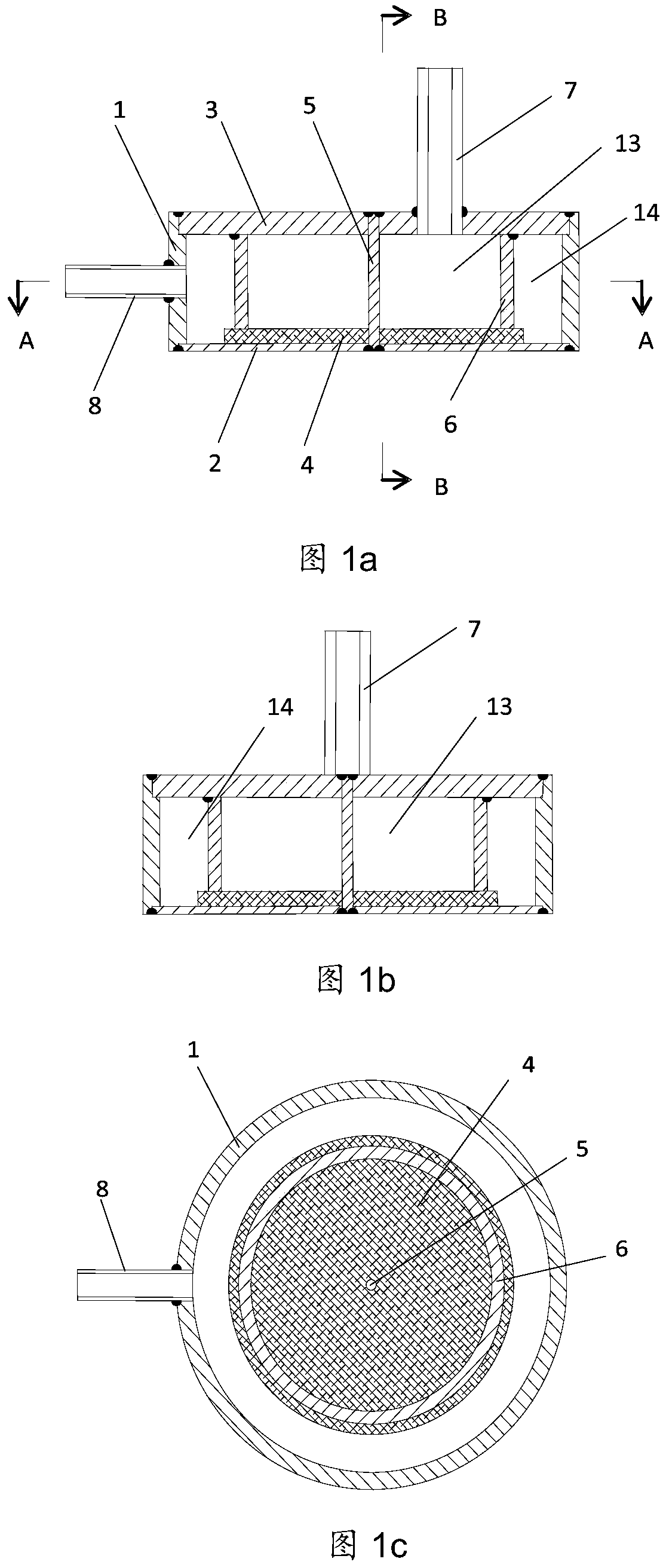
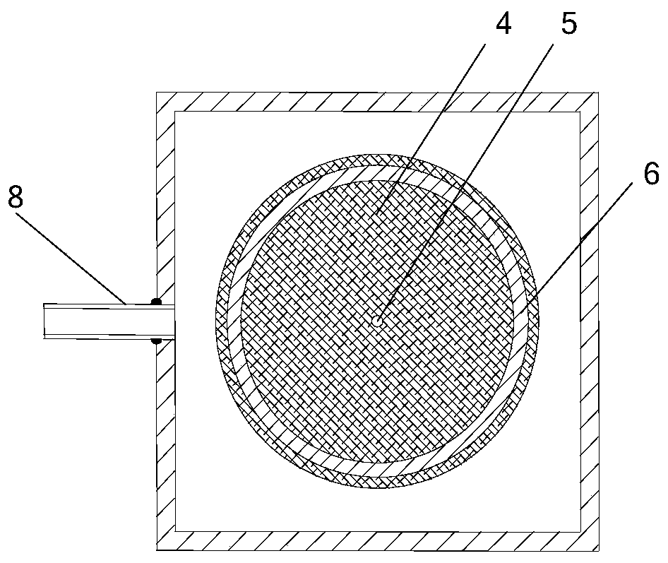
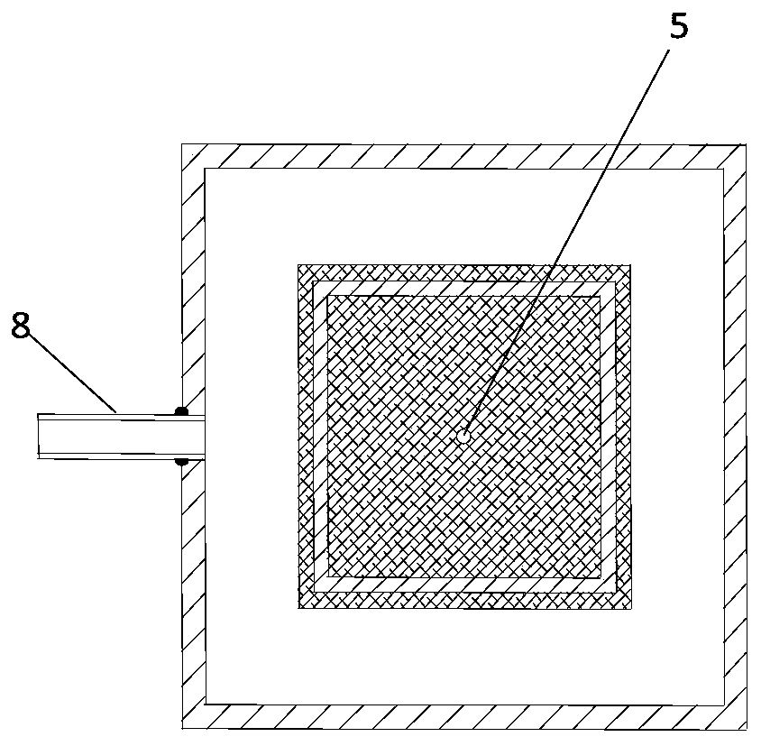
[0045] Such as figure 1 Shown are three side views of the evaporator of the loop heat pipe of the present invention, wherein figure 1 a is the main view, figure 1 b is a side view, figure 1 c is a partial top view, as can be seen from the figure, the evaporator of the loop heat pipe of the present invention includes an outer cylinder wall 1, a heat-absorbing surface 2, an upper end cover 3, a capillary core 4, a reinforcing column 5, a vapor-liquid isolation barrel 6, and a steam outflow pipe joint 7 and a liquid return pipe joint 8, wherein the vapor-liquid isolation barrel 6 is a cylindrical thin-walled structure with openings at both ends, the upper end cover 3 and the heat-absorbing surface 2 are respectively located on the upper and lower end surfaces of the outer cylinder wall 1, the outer cylinder wall 1, the heat-absorbing surface The...


PUM


Abstract

The invention relates to an evaporator of a loop heat pipe and a preparation method of the evaporator. The evaporator comprises an outer cylindrical wall, a heat absorption face, an upper end cover, a capillary core and a vapor-liquid isolation barrel with openings in the two ends. A cavity structure is formed by the outer barrel wall, the heat absorption face and the upper end cover, the capillary core is attached to the heat absorption face, one end of the vapor-liquid isolation barrel is in contact with the surface of the capillary core, the capillary core is pressed on the heat absorption face, and the other end of the vapor-liquid isolation barrel is fixedly connected with the upper end cover; the cavity structure formed by the outer barrel wall, the heat absorption face and the upper end over is divided into two parts through the vapor-liquid isolation barrel, a vapor cavity is formed in the vapor-liquid isolation barrel, and a liquid cavity is formed outside the vapor-liquid isolation barrel. The evaporator is ingenious in structural design and excellent in performance, it is effectively guaranteed that vapor and liquid in the evaporator are separated, certain positive pressure and negative pressure can be borne, that is, a coupling face is not likely to deform, the machining method is simple and reliable, and volume production is convenient.

Description

technical field [0001] The invention relates to an evaporator of a loop heat pipe and a preparation method thereof, and belongs to the technical field of loop heat pipes in engineering thermophysics and heat pipe disciplines. Background technique [0002] The heat pipe is a high-performance heat transfer element, which is a device that continuously transfers heat from the heat source to the heat sink by the evaporation, condensation and reflow of the internal working medium (working fluid). Heat pipes are used in a wide range of applications. With the development of technology, the demand for heat pipes continues to grow. [0003] A loop heat pipe (Loop Heat Pipe, LHP) is generally composed of an evaporator, a compensation chamber, an isolator, a condenser, a steam pipe and a liquid pipe. Steamer design and fabrication methods are key to achieving the desired performance of the LHP. [0004] There are various structures of heat pipes, and LHP is a kind of heat pipe. At pr...

Claims


Application Information

Patent Timeline
Patent Type & Authority Patents(China)
IPC IPC(8): F25B39/02F28D15/04F28F9/26F25B43/00
CPCF28D15/0266
Inventor 曲伟陈思员薛志虎俞继军
Owner CHINA ACAD OF AEROSPACE AERODYNAMICS
Why Eureka
Try Eureka