Supercharge Your Innovation With Domain-Expert AI Agents!

Constant-current type signal conditioning circuit of resistance-sensitive sensor

A sensor signal, conditioning circuit technology, applied in the direction of adjusting electrical variables, instruments, control/regulating systems, etc., can solve the problems of resistance-sensitive sensor detection results interference, troublesome debugging and maintenance, difficult parameter matching, etc., to achieve good versatility, Easy to chip and set circuit parameters, low cost effect

Active Publication Date: 2017-01-04
徐州戴胜信息科技有限公司
View PDF5 Cites 0 Cited by
  • Summary
  • Abstract
  • Description
  • Claims
  • Application Information

AI Technical Summary

Problems solved by technology

At present, the commonly used schemes and their shortcomings in the circuit of resistance-sensitive sensors mainly lie in: (1) Scheme 1: the scheme of using regulated power supply + operational amplifier processing circuit. It is the objective noise and line voltage drop in the voltage of the modern switching regulated power supply that will seriously interfere with the detection results of the resistance-sensitive sensor.
(2) Scheme 2: The scheme of using steady-current source power supply + operational amplifier processing circuit, that is, the power supply for the resistance-sensitive sensor adopts the steady-current power supply based on the operational amplifier and triode drive, and the signal processing adopts the circuit mainly based on the operational amplifier. The circuit is relatively complex, with many components, difficult parameter matching, troublesome debugging and maintenance

Method used


Image

  • Constant-current type signal conditioning circuit of resistance-sensitive sensor

Examples


Embodiment Construction

[0010] The present invention will be further described below in conjunction with accompanying drawing.

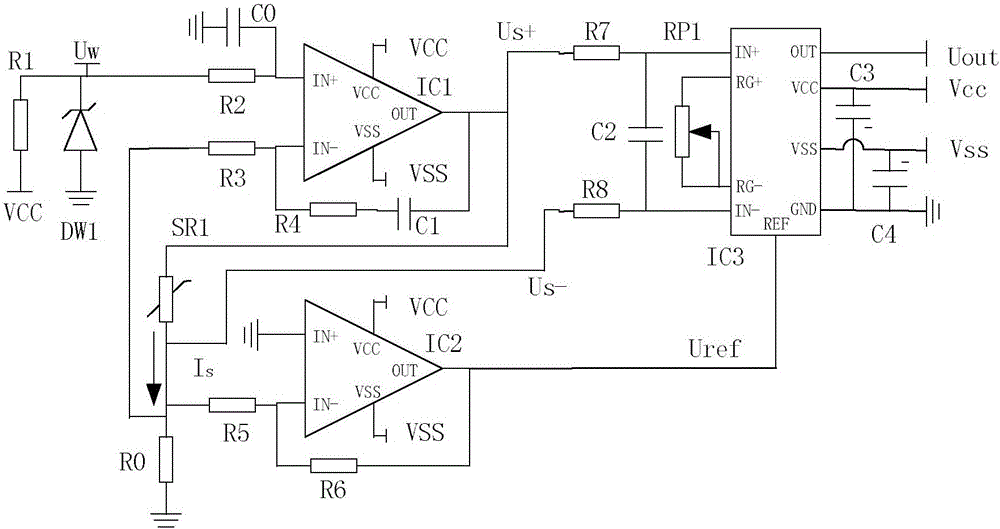
[0011] Such as figure 1 As shown in FIG. 1 , a signal conditioning circuit for a constant-current resistive sensor includes a sensor power supply circuit and a sensing signal conditioning circuit.

[0012] The sensor power supply circuit includes a steady current operational amplifier IC1, a voltage regulator tube DW1, a resistance sensitive sensing element SR1, a steady current resistor R1, a positive terminal resistor R2, a negative terminal resistor R3, an adjustment resistor R4, a reference resistor R0, a voltage stabilizing capacitor C0, Adjust the capacitor C1, one end of the constant current resistor R1 is connected to the positive power supply terminal VCC of the circuit, the other end of the constant current resistor R1 is connected to the cathode of the voltage regulator tube DW1, and one end of the positive terminal resistor R2, and the anode of the voltage regul...


PUM


Abstract

The invention discloses a constant-current type signal conditioning circuit of a resistance-sensitive sensor. The constant-current type signal conditioning circuit comprises a sensor power source circuit and a sensing signal conditioning circuit; specifically, the power supply current of a resistance-sensitive sensing element is performed with floating control by a proportional-integral controller mainly using a stable-current operational amplifier, and completely depends on the voltage-stable value of a voltage-stable tube and the resistance value of a reference resistor in a formula; in the signal conditioning circuit mainly using a phase inverter and an instrument operational amplifier, an output signal of the phase inverter is used for offsetting an initial output signal of the resistance-sensitive sensing element under the condition of stable-current power supply; the effective resistance value of a gain potentiometer is adjusted, and the instrument operational amplifier is used for converting the range of measured physical quantity into the voltage signal output within the required standard voltage modulation range. The constant-current type signal conditioning circuit has the advantages that the structure is simple, the number of devices is fewer, the real-time property is strong, the size is small, the cost is low, the reliability is high, the universality is good, and the chip application is easy.

Description

technical field [0001] The invention belongs to the field of industrial measurement and control, and relates to a circuit, in particular to a constant-current resistance-sensitive sensor signal conditioning circuit, which is suitable for various application occasions where the resistance-sensitive sensor is used for real-time detection of related physical quantities to be measured. Background technique [0002] Various resistance-sensitive sensing elements such as force-sensitive resistors and thermal resistors are widely used. The performance of sensors based on resistance-sensitive sensing elements depends on the stability of the power supply circuit and signal conditioning circuit, the signal-to-noise ratio, and the difficulty of circuit tuning. degree etc. At present, the commonly used schemes and their shortcomings in the circuit of resistance-sensitive sensors mainly lie in: (1) Scheme 1: the scheme of using regulated power supply + operational amplifier processing cir...

Claims


Application Information

Patent Timeline
IPC IPC(8): G05F1/56
CPCG05F1/56
Inventor 陈德传高明煜
Owner 徐州戴胜信息科技有限公司
Features
  • R&D
  • Intellectual Property
  • Life Sciences
  • Materials
  • Tech Scout
  • Unparalleled Data Quality
  • Higher Quality Content
  • 60% Fewer Hallucinations
Learn More