
A vertical nanowire device with sheath channel structure and its preparation method

A channel structure and nanowire technology, which is applied in semiconductor/solid-state device manufacturing, semiconductor devices, electrical components, etc., can solve the problems of increasing device power consumption, difficult control of channel cross-sectional morphology, and device performance degradation, etc. Small leakage current and improved short channel effect control ability

Active Publication Date: 2019-07-19
PEKING UNIV
View PDF5 Cites 0 Cited by
  • Summary
  • Abstract
  • Description
  • Claims
  • Application Information

AI Technical Summary

Problems solved by technology

[0005] (1) If the diameter of the vertical channel is large, there will be a leakage path in the center of the channel away from the gate control area, which increases the power consumption of the device; but if you want to form a vertical channel with a smaller diameter and a large aspect ratio by etching The channel itself poses a great challenge to the etching process, and the cross-sectional morphology of the channel formed by etching is difficult to control, resulting in the degradation of the consistency of device characteristics, and the channel damage caused by etching, causing further degradation of device performance;

Method used


Image

  • A vertical nanowire device with sheath channel structure and its preparation method
  • A vertical nanowire device with sheath channel structure and its preparation method
  • A vertical nanowire device with sheath channel structure and its preparation method

Examples


Embodiment Construction

[0084] Below in conjunction with accompanying drawing, further describe the present invention through embodiment, but do not limit the scope of the present invention in any way.

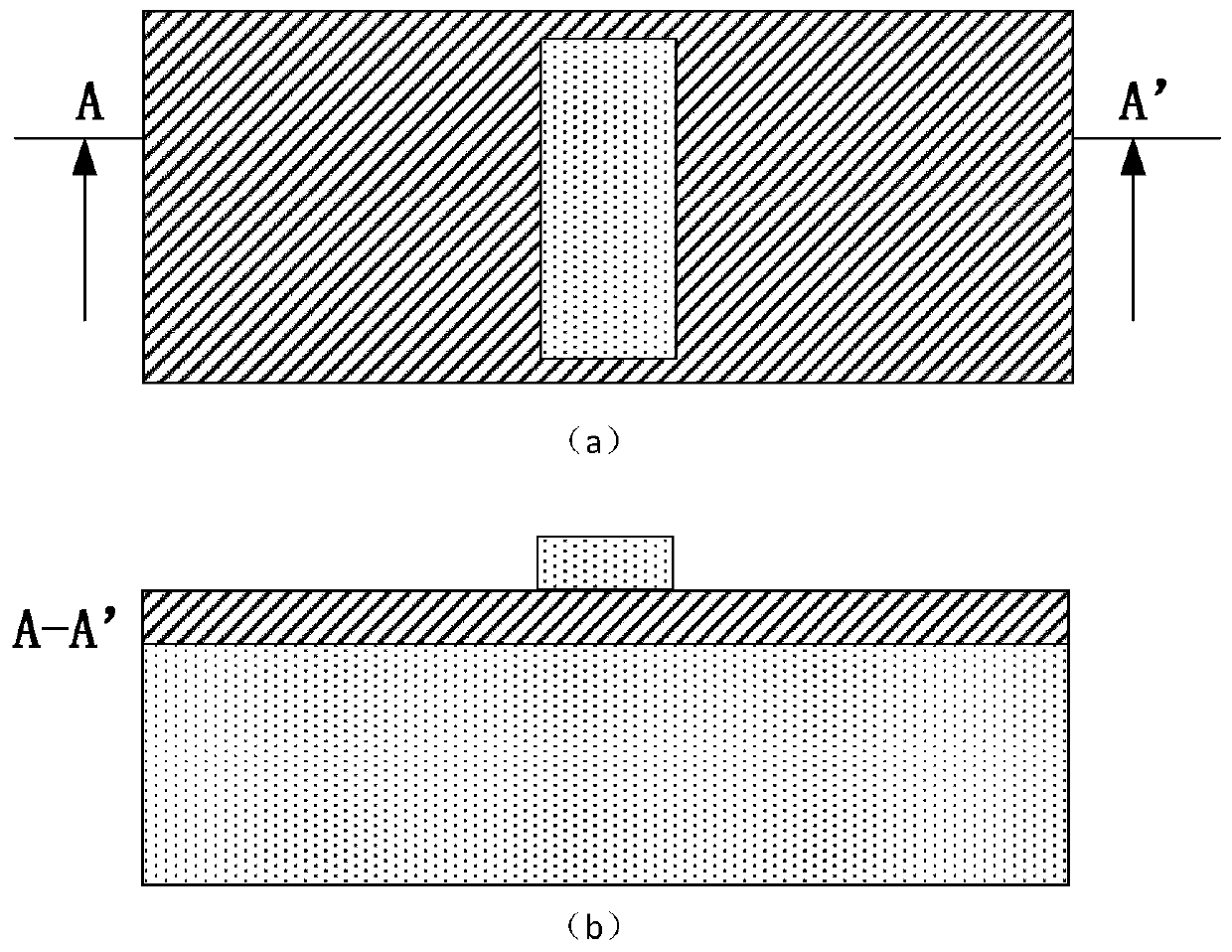
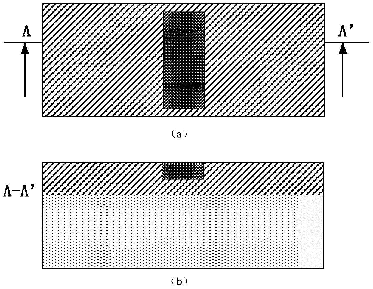
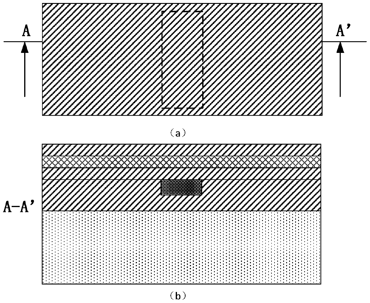
[0085] The invention provides a vertical nanowire device with a sheath channel structure and a preparation method thereof, which combines etching through holes, depositing channel materials, and filling silicon dioxide to obtain an integrated vertical nanowire device with a sheath channel structure; Including providing a semiconductor substrate to realize device isolation; forming a heavily doped "lower active region"; depositing dummy gate stacks; forming vertical sheaths by etching vias, depositing channel materials, and filling silicon dioxide Layer channel structure; form the heavily doped "upper active region" of the device by deposition and etching; remove the dummy gate, deposit HK, MG and form the gate electrode; form metal contacts at each end of the device; follow-up according to the existin...


PUM


Abstract

The invention discloses a vertical nanowire device with a sheath channel structure and a preparation method of the vertical nanowire device. A through hole is etched, a channel material is deposited, and silicon dioxide is filled to obtain the vertical nanowire device integrated with the sheath channel structure. The preparation method comprises the following steps: providing a semiconductor substrate to isolate devices; forming a heavily doped lower active region; depositing a pseudo gate stack; forming the sheath channel structure by etching the through hole, depositing the channel material and filling the silicon dioxide; forming a heavily doped upper active region by depositing and etching; removing pseudo gates, depositing HK and MG and forming a gate electrode; enabling metals of various ends of the formed devices to be in contact with one another; and integrating the devices according to an existing rear end process. Short channel effect control capability of the devices can be improved effectively, and leakage current is reduced; thicknesses, sectional area sizes and morphologies of channels of the devices can be controlled accurately, and the properties of the devices are improved by a rear gate process.

Description

technical field [0001] The invention belongs to the technical field of ultra-large-scale integrated circuit manufacturing, and relates to a vertical nanowire device with a sheath channel structure and a preparation method thereof. The method combines etching through holes, depositing channel materials, and filling silicon dioxide to realize Vertical nanowire device integration of sheathed channel structures. Background technique [0002] When semiconductor devices enter the 22nm technology generation, the horizontal channel three-dimensional multi-gate device (Multi-gate MOSFET, MuGFET) represented by the fin field effect transistor (FinFET), with its outstanding ability to suppress the short channel effect, high integration density , Compatible with traditional CMOS technology and other advantages, it has become the mainstream of semiconductor devices. However, when moving towards smaller technology nodes, horizontal channel three-dimensional multi-gate devices face challe...

Claims


Application Information

Patent Timeline
Patent Type & Authority Patents(China)
IPC IPC(8): H01L29/78H01L21/336H01L29/10
CPCH01L29/1037H01L29/66795H01L29/785
Inventor 黎明陈珙杨远程黄如
Owner PEKING UNIV
Learn More