A catheter handle used for an implant conveying system

A delivery system and implant technology, applied in the field of minimally invasive interventional medical devices, can solve problems such as easy to hide dirt, form air thrombus, and no indication, so as to avoid the risk of dirt hiding, avoid the formation of air thrombus, The effect of external smoothing

Active Publication Date: 2017-01-11
SHANGHAI VASOLUTIONS MEDTECH CO LTD
View PDF10 Cites 11 Cited by
  • Summary
  • Abstract
  • Description
  • Claims
  • Application Information

AI Technical Summary

Problems solved by technology

However, the catheter handle in this patent has a sliding shaft on the outer surface of the thread, and the thread on the outer surface has the problems of easily hiding dirt and feeling uncomfortable; at the same time, the patent for the catheter handle does

Method used


Image

  • A catheter handle used for an implant conveying system
  • A catheter handle used for an implant conveying system
  • A catheter handle used for an implant conveying system

Examples


Embodiment 1

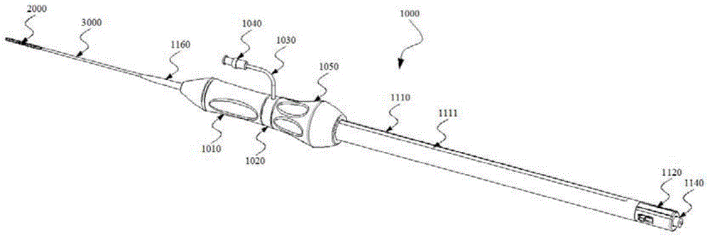
[0062] Make the stress diffusion tube 1160, the front handle 1010, the snap ring 1020, the rear handle 1050, the threaded fastener 1060, the front slider 1070, the rear slider 1080, the sliding shaft 1110, the tail end sleeve 1130 and the one-way valve by injection molding 1040;

[0063] Manufacturing shrapnel 1090 and spring 1100 by machining;

[0064] The infusion tube 1030, the outer sheath tube 3000 and the push tube 6000 are produced by extrusion molding;

[0065] The nickel-titanium alloy self-expanding stent 2000 was fabricated by laser cutting, heat treatment and electrochemical polishing;

[0066] One end of the infusion tube 1030 is bonded to the one-way valve 1040 with glue, and the other end passes through the snap ring hole 1021 of the snap ring 1020 ( Figure 9 ) and then use glue to bond the front slider 1070; use glue to bond one end of the outer sheath 3000 to the front slider 1070, and pre-compress the self-expanding stent 2000 into the other end of the out...

Embodiment 2

[0075] The stress diffusion tube 1160, the front handle 1010, the snap ring 1020, the rear handle 1050, the threaded fixing piece 1060, the front slider 1070, the rear slider 1080, the sliding shaft 1110, the tail end sleeve 1120, and the one-way valve are produced by injection molding 1040;

[0076] Manufacturing shrapnel 1090 and spring 1100 through machining;

[0077] The infusion tube 1030, the outer sheath tube 3000, and the push tube 6000 are produced by extrusion molding;

[0078] The nickel-titanium alloy self-expanding stent 2000 was fabricated by laser cutting, heat treatment and electrochemical polishing;

[0079] One end of the infusion tube 1030 is bonded to the one-way valve 1040 with glue, and the other end passes through the snap ring hole 1021 of the snap ring 1020 ( Figure 9 ) after bonding with the front slider 1070 with glue; glue one end of the outer sheath tube 3000 with the front slider 1070, and pre-compress the self-expanding stent 2000 into the other...


PUM


Abstract

The invention provides a catheter handle used for an implant conveying system. The catheter handle comprises a slide shaft, a front slide and a rear slider, and rear handle. The slide shaft is a hollow tubular component provided with at least one axial slot; the slide shaft has a proximal end and a distal end; the front slider and the rear slider are arranged in the slide shaft and are in slide connection with the slide shaft; the front slider is close to the distal end of the slide shaft; each of the front slider and the rear slider is provided with a middle hole allowing penetration of a push tube; an elastic part is arranged between the front slider and the rear slider; the portion, passing the axial slots, of the rear slider is provided with a first transmission mechanism; the rear handle is rotatably arranged on the outer portion of the slide shaft; the inside of the rear handle is provided with a second transmission mechanism which matches and engages with the first transmission mechanism on the rear slider. Under the control of the catheter handle used for an implant conveying system, such implants as stents can be released at focus parts accurately; the risk of dirt hiding is avoided; the handholding comfort level is increased; the formation of air thrombi can be effectively avoided.

Description

technical field [0001] The invention relates to the field of minimally invasive interventional medical devices, in particular to a catheter handle for an implant delivery system. Background technique [0002] Minimally invasive interventional surgery refers to the use of catheters, stents, guide wires and other interventional devices to complete the treatment of lesions in blood vessels or cavities under the guidance of various imaging equipment. The implementation of minimally invasive interventional therapy depends on various minimally invasive implants, including stents, occluders, artificial valves and so on. Stents in minimally invasive implants usually include balloon-expandable and self-expandable stents. Self-expandable stents are increasingly used in intravascular diseases such as vascular stenosis and hemangioma due to their strong resistance to deformation. Interventional therapy, especially for the treatment of vascular lesions in frequently active parts, such a...

Claims


Application Information

Patent Timeline
IPC IPC(8): A61F2/966A61B17/00
Inventor 韩建超张琳琳李中华祁勇翔丁双喜苗铮华
Owner SHANGHAI VASOLUTIONS MEDTECH CO LTD
Why Eureka
Try Eureka