Thin-walled cylinder anti-deformation clamp and laser cladding machine for repairing cracks

A thin-walled cylinder and anti-deformation technology, applied in the field of machinery, can solve the problems of poor cylinder coaxiality, easy deformation coaxiality of cylindrical welds, etc., and achieve the effect of improving practical performance and high welding seam quality.

Active Publication Date: 2017-01-11
PUTIAN UNIV
View PDF8 Cites 25 Cited by
  • Summary
  • Abstract
  • Description
  • Claims
  • Application Information

AI Technical Summary

Problems solved by technology

[0005] For this reason, it is necessary to provide a thin-walled cylinder anti-deformation fixture to solve the problems of poor coaxiality of t...

Method used


Image

  • Thin-walled cylinder anti-deformation clamp and laser cladding machine for repairing cracks
  • Thin-walled cylinder anti-deformation clamp and laser cladding machine for repairing cracks
  • Thin-walled cylinder anti-deformation clamp and laser cladding machine for repairing cracks

Examples


Embodiment 1

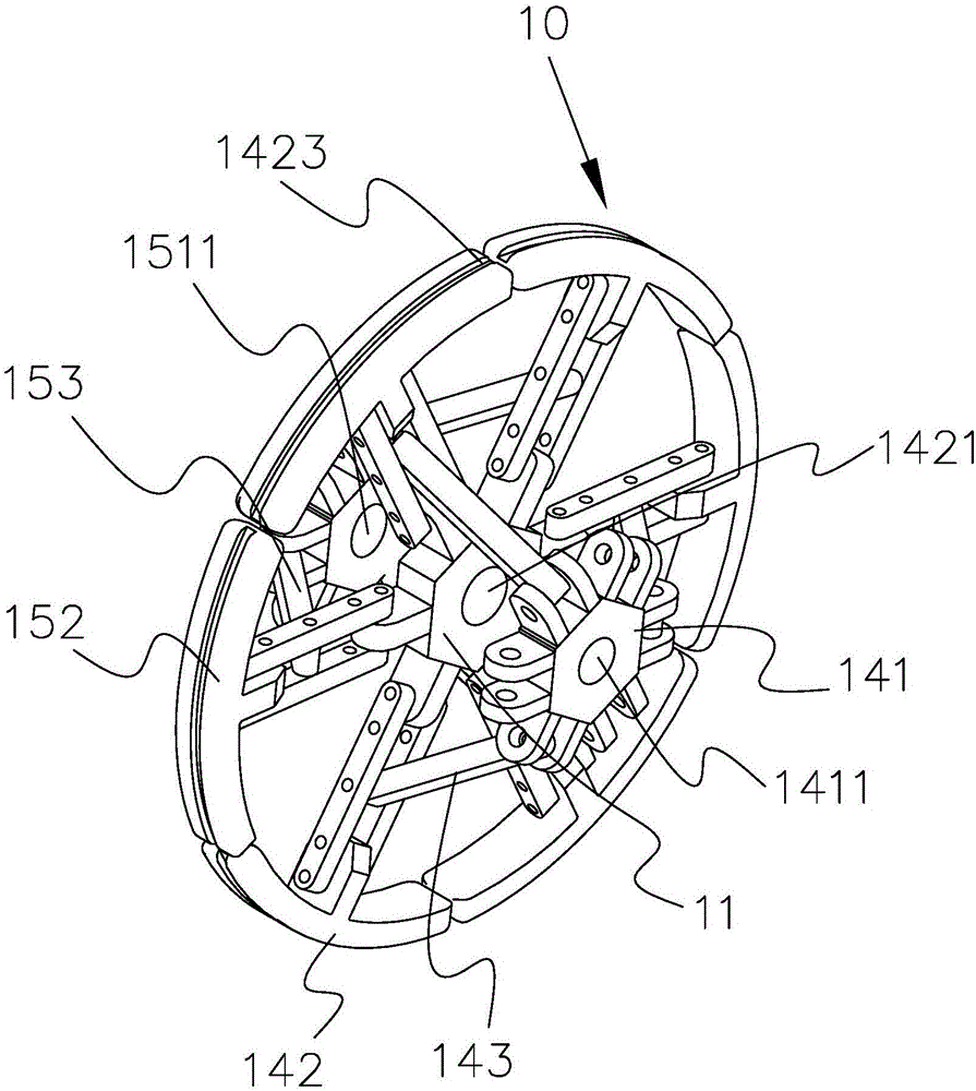
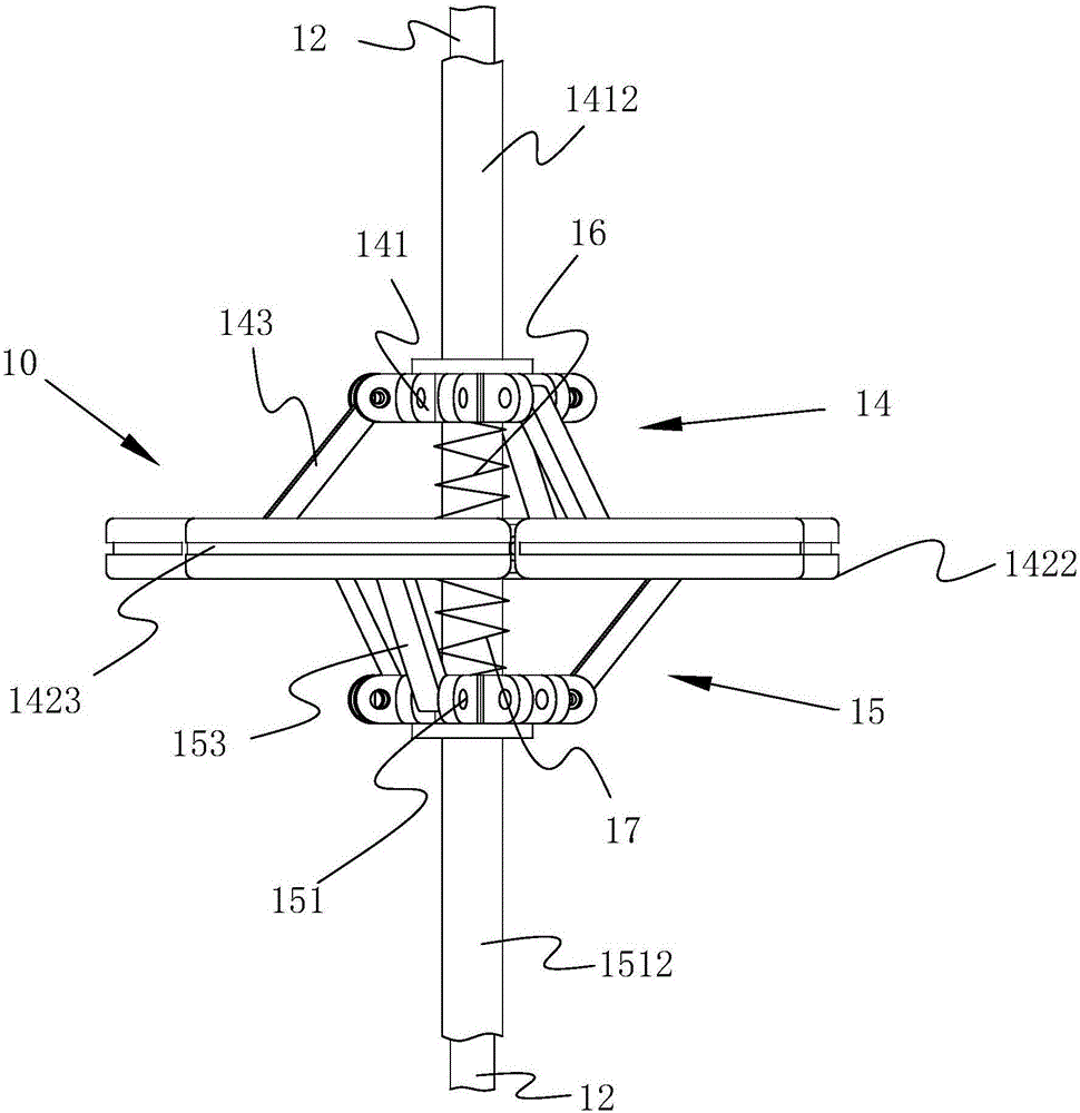
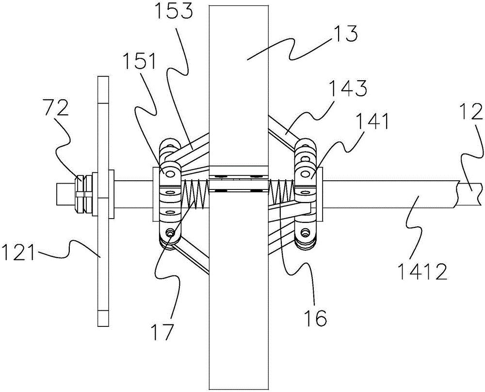
[0088] see figure 1 , figure 2 , image 3 as well as Figure 4 , a thin-walled cylindrical anti-deformation fixture of the present invention, comprising a central plate 11, a central shaft 12, an outer hoop 13, a first umbrella stand mechanism 14 and a second umbrella stand mechanism 15;

[0089] The first umbrella stand mechanism 14 includes a first end plate 141, a first support ring 142 and a first connecting rod 143, a first shaft hole 1411 is provided at the center of the first end plate, and a first shaft hole 1411 is provided at the center of the center plate. There is a second shaft hole 1421, a first push rod 1412 is arranged on the end surface of the first end plate, a first spring 16 is arranged between the center plate and the first end plate, and the first support ring and the center plate Hinged, one end of the first connecting rod is hinged at the middle of the first support ring, and the other end of the first connecting rod is hinged at the first end plate...

Embodiment 2

[0099] see Figure 6 as well as Figure 7 , the present invention provides a laser cladding machine for repairing cracks, including a thin-walled cylindrical anti-deformation fixture 10, a workbench 20, a laser 30, a controller 31 and a frame 32;

[0100] The thin-walled cylindrical anti-deformation fixture includes a central plate, a central shaft, an outer hoop, a first umbrella stand mechanism and a second umbrella stand mechanism;

[0101] The first umbrella stand mechanism includes a central plate 11, a central shaft 12, an outer hoop 13, a first umbrella stand mechanism 14 and a second umbrella stand mechanism 15;

[0102] The first umbrella stand mechanism 14 includes a first end plate 141, a first support ring 142 and a first connecting rod 143, a first shaft hole 1411 is provided at the center of the first end plate, and a first shaft hole 1411 is provided at the center of the center plate. There is a second shaft hole 1421, a first push rod 1412 is arranged on the ...


PUM


Abstract

The invention provides a thin-walled cylinder anti-deformation clamp which comprises a center plate, a center shaft, an outer shroud ring, a first umbrella stand mechanism and a second umbrella stand mechanism. The first umbrella stand mechanism and the second umbrella stand mechanism are the same in structure and connection arrangement. The second umbrella stand mechanism comprises a second end plate, second supporting rings and second connecting rods. A third axle hole is formed in the center position of the second end plate. A first axle hole, a second axle hole and the third axle hole are sequentially formed in the center shaft. A second push rod is arranged on the end face of the second end plate. A second spring is arranged between the center plate and the second end plate. According to the technical scheme, by means of cooperation of a three-claw chuck, an ejection piece and the clamp, the coaxiality of welded cylinders is high, butt weld joints cannot deform, and the weld joint quality is high; and meanwhile, a tail frame can move along ground guide rails, and therefore the thin-walled cylinder anti-deformation clamp can be suitable for welding of thin-walled cylinders different in specification length, and the practicality performance is greatly improved.

Description

technical field [0001] The invention relates to the field of machinery, in particular to a thin-walled cylindrical anti-deformation fixture and a laser cladding machine for repairing cracks. Background technique [0002] Nowadays, for the welding of thin-walled cylinders, it is generally clamped with a three-jaw chuck, four-jaw chuck or roller rolling for direct clamping. After the clamping is completed, welding is performed. This not only consumes man-hours, but also is easy to Deformation, which in turn leads to wrong welds, and it is also difficult to grasp the quality of the welded welds, resulting in poor coaxiality of the welded cylinder. And when working, the actual working size of the workbench cannot be changed, so that the limitations of welding thin-walled cylinders are relatively large, but the technical side can clamp the cylinder to be welded so that the weld seam is butted with the axis, and at the same time Internal and external clamping makes the butt welds...

Claims


Application Information

Patent Timeline
IPC IPC(8): B23K26/282B23K26/70B23K31/00B23K37/053
CPCB23K26/282B23K26/702B23K31/003B23K37/0531
Inventor 陈金国范剑红林金兰陈春华宋一然陈庆堂林舒萍
Owner PUTIAN UNIV
Why Eureka
Try Eureka