Laser drilling and drilled-hole filling system and method

A laser drilling and filling system technology, applied in laser welding equipment, welding equipment, metal processing equipment, etc., can solve the problem of small size, inability to achieve optical components, and inability to adjust the rotation angle of high-speed rotating beams, etc. problem, to achieve the effect of improving processing efficiency

Active Publication Date: 2017-01-11
张立国
View PDF6 Cites 10 Cited by
  • Summary
  • Abstract
  • Description
  • Claims
  • Application Information

AI Technical Summary

Problems solved by technology

[0003] The high-speed rotating optical element is used to rotate the rotating beam for laser processing. Due to the dynamic balance problem, the optical element cannot be very complicated and the size is not large, so the rotation angle of the high-speed r

Method used


Image

  • Laser drilling and drilled-hole filling system and method
  • Laser drilling and drilled-hole filling system and method
  • Laser drilling and drilled-hole filling system and method

Examples


Embodiment 1

[0055] Embodiment 1. A silicon wafer laser drilling system. Combine below Figure 1-Figure 4 This embodiment will be described in detail.

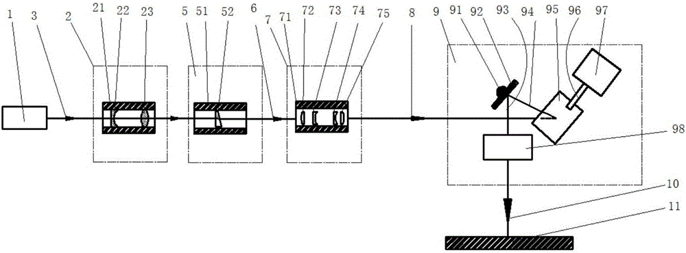
[0056] see figure 1 , a silicon wafer laser drilling system in this embodiment includes a laser light source module 1, an incident beam rotation movement module 5, an adjustable beam rotation angle compression ratio module 7, and a laser focusing and focus switching module 9;

[0057] The laser light source module 1 is used to generate an incident light beam 3, which is incident on the incident light beam rotation movement module 5;

[0058] The incident light beam rotation movement module 5 is used for rotationally modulating the incident light beam 3 to output a rotating light beam to form a first light beam 6 that rotates around the optical axis of the incident light beam 3, and the first light beam 6 is incident on the The beam rotation angle compression magnification adjustable module 7, wherein the full angle of rotation of the fi...

Embodiment 2

[0077] Embodiment 2. A laser drilling system for low temperature co-fired ceramics.

[0078] The laser drilling system of this embodiment is as Figure 5 As shown, in addition to the module in the above-mentioned embodiment 1, it also includes a beam expansion magnification compensation module 2, the laser light source module 1 emits an exit laser beam 4, the exit laser beam 4 enters the beam expansion magnification compensation module 2, and outputs an incident beam 3 .

[0079] Different from Embodiment 1, a beam expansion magnification compensation module 2 is provided before the incident beam rotation movement module 5; when the beam rotation angle compression magnification adjustable module 7 compresses the rotation angle of the first beam 6 at a large , the beam expansion magnification compensation module 2 performs small-magnification beam expansion on the exit laser beam 4, or, when the beam rotation angle compression magnification adjustable module 7 performs small-m...

Embodiment 3

[0084] Embodiment 3, a laser drilling and drilling filling method.

[0085] see Figure 6 , the borehole filling method provided in this embodiment includes the following steps:

[0086] S1, the incident beam generated by the laser light source module enters the incident beam rotation movement module;

[0087] S2, the incident light beam rotation movement module rotates and modulates the incident light beam to output a rotating light beam to form a first light beam that rotates around the optical axis of the incident light beam, and the first light beam enters the beam rotation angle compression magnification adjustable module , wherein the full angle of rotation of the optical axis of the first light beam is less than 30 milliradians;

[0088] S3, the beam rotation angle compression magnification adjustable module expands the first beam and compresses the spatial rotation angle of the first beam, outputs the second beam with a compressed rotation angle and enters the laser ...


PUM

PropertyMeasurementUnit
Thicknessaaaaaaaaaa
Diameteraaaaaaaaaa
Diameteraaaaaaaaaa

Abstract

The invention discloses a laser drilling and drilled-hole filling system and method. The laser drilling and drilled-hole filling system comprises a laser light source module, an incident beam rotary movement module, a beam rotation angle compression ratio adjustable module and a laser focusing and focus switching module. As the beam rotation angle compression ratio adjustable module is introduced, during high-speed rotation of laser, the beam rotation angle compression ratio of the beam rotation angle compression ratio adjustable module is adjusted to realize focus rotary movement track diameter adjustment of a focused beam, and the focus rotary movement track diameter is in adjustable perfect combination with the aperture of a drilled hole; a beam expansion ratio compensation module is introduced, so that when the beam rotation angle compression ratio adjustable module performs rotation angle compression on an incident rotary beam, the entry light spot diameter of the incident rotary beam is changed correspondingly, the stability of the focus light spot diameter of the focused beam is guaranteed, and the stability and the processing effect of the laser processing technology are facilitated.

Description

technical field [0001] The invention relates to the field of laser processing, in particular to a laser drilling and drilling filling system and method. Background technique [0002] In the field of laser drilling, the laser focus is switched between holes. At present, galvanometer scanning is a relatively mature and fastest switching method, which is manifested in high acceleration and deceleration, displacement linear velocity and positioning speed. The two-dimensional displacement platform is a very slow method, which is rarely used in general. [0003] The high-speed rotating optical element is used to rotate the rotating beam for laser processing. Due to the dynamic balance problem, the optical element cannot be very complicated and the size is not large, so the rotation angle of the high-speed rotating beam cannot be adjusted, but in practical applications , the diameter of the hole to be processed does need to be changed at any time, and there is a huge challenge bet...

Claims


Application Information

Patent Timeline
IPC IPC(8): B23K26/382B23K26/386B23K26/046B23K26/70
CPCB23K26/046B23K26/382B23K26/389B23K26/702
Inventor 张立国
Owner 张立国
Why Eureka
Try Eureka