Symmetrical three-degree-of-freedom movement coupling mechanism

A technology of coupling mechanism and degrees of freedom, applied in the field of coupling mechanism, can solve the problem of not forming a comprehensive method of configuration, and achieve the effect of good application prospect, easy control and high bearing capacity

Inactive Publication Date: 2017-01-11
BEIJING UNIV OF TECH
View PDF5 Cites 9 Cited by
  • Summary
  • Abstract
  • Description
  • Claims
  • Application Information

AI Technical Summary

Problems solved by technology

However, the current research on the configuration synthesis of coupling mechanisms is still in the basic stage
Although some individual mechanism design methods have been proposed one after another, they are far from forming a traditional and regular configuration synthesis method.

Method used


Image

  • Symmetrical three-degree-of-freedom movement coupling mechanism

Examples


Embodiment Construction

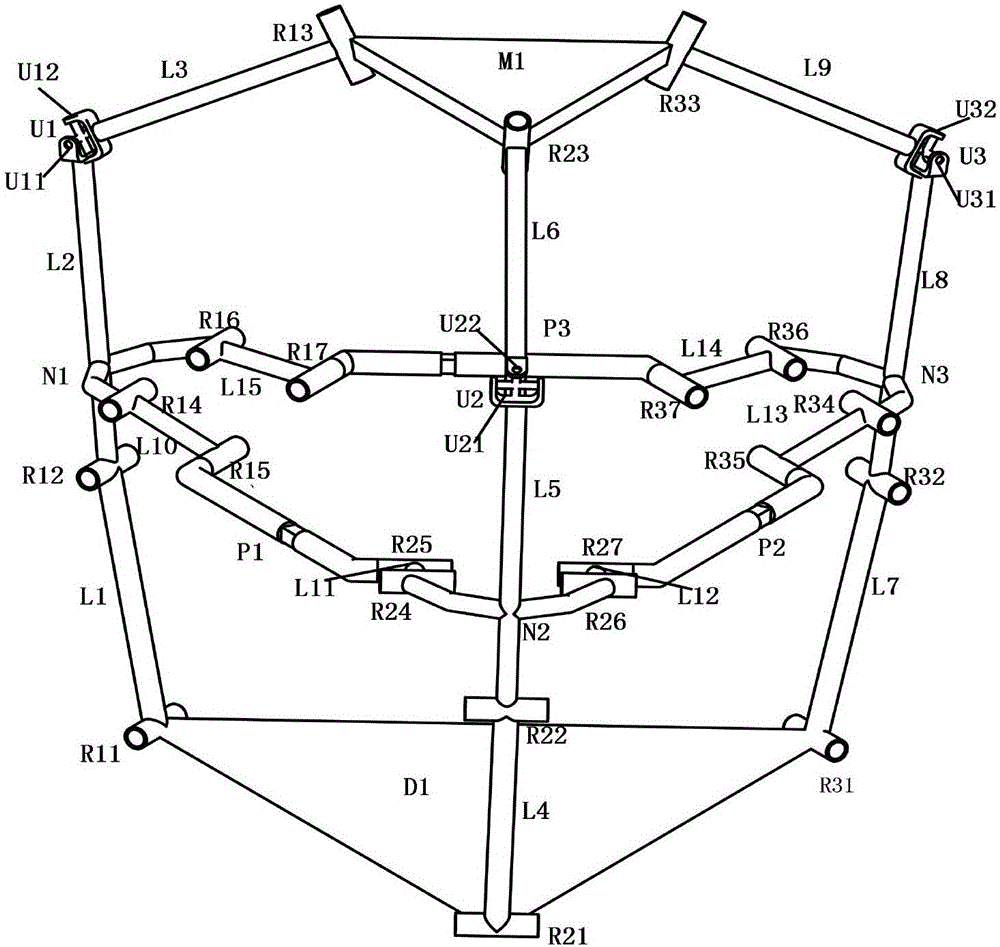
[0028] Such as figure 1 As shown, the first branch includes the first revolving pair (R11) of the frame, the revolving pair (R12) with the coupling node bar of the first branch, the Hooke hinge U1, and the first revolving pair (R13) of the moving platform; the frame The first revolving pair (R11) and the revolving pair (R12) with the first branch coupling node bar are connected through the first connecting rod (L1), and the revolving pair (R12) with the first branch coupling node bar is connected to Hooke The first revolving pair (U11) of the hinge U1 is connected through the second connecting rod (L2), and the second revolving pair (U12) of the Hooke hinge U1 and the first revolving pair (R13) of the moving platform are connected through the third connecting rod (L3) connect. The first revolving pair (R11) of the frame, the revolving pair (R12) of the first branch coupling node bar, and the first revolving pair (U11) of the Hooke hinge U1 are parallel to each other. The sec...


PUM


Abstract

Asymmetrical three-degree-of-freedom movement coupling mechanism is based on a symmetrical three-degree-of-freedom movement paralleling mechanism and adopts the technical scheme that the coupling mechanism is constructed in the mode that coupling rod groups are added among paralleling mechanismbranched chains. For facilitating adding of the coupling branched chains to connecting rods, a 3-RRUR paralleling mechanism containing more R pairs is used as a basis, appropriate coupling node positions are selected from the coupling branched chains under the situation that the degree of freedom of the mechanism is ensured, and the appropriate coupling rod groups are added to form the symmetrical three-degree-of-freedom movement coupling mechanism. The symmetrical three-degree-of-freedom movement coupling mechanism has the advantages of being large in rigidity, good in carrying capacity, stable in movement and convenient to assemble and maintain, and a new thought is provided for configuration integration of multiple loop coupling mechanisms.

Description

technical field [0001] The invention is a coupling mechanism obtained by adding a coupling rod group based on a symmetrical parallel mechanism, relates to the technical field of mechanism application, and in particular relates to a robot actuator with three-degree-of-freedom movement. Background technique [0002] The development of institutions has gone through a process from simple to complex, and the most effective way to innovate institutions is to systematically synthesize their configurations. In some high-strength and heavy-duty workplaces that require heavy machinery equipment, it is often required that the machine has a high mechanical strength, simple structure, low cost, and easy maintenance, and the end effector needs to meet the requirements of smooth movement and easy control. The existing parallel mechanism has the advantages of strong bearing capacity, high rigidity, and low inertia, but the working space is limited; the series mechanism has a large working s...

Claims


Application Information

Patent Timeline
Patent Type & Authority Applications(China)
IPC IPC(8): B25J9/00
CPCB25J9/0045
Inventor 曹亚柯刘婧芳张双
Owner BEIJING UNIV OF TECH
Why Eureka
Try Eureka