Method for mining thin inter bed oil shale
A technology for oil shale and oil shale formations, applied in the field of oil and gas exploitation, can solve problems such as low heating efficiency, difficult cracking, and difficulty in reaching the temperature required for kerogen pyrolysis with ordinary water vapor
- Summary
- Abstract
- Description
- Claims
- Application Information
AI Technical Summary
Problems solved by technology
Method used
Image
Examples
Embodiment 1
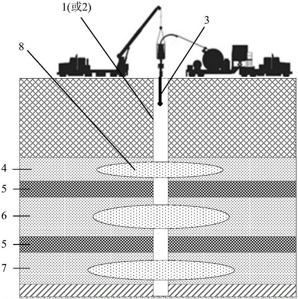
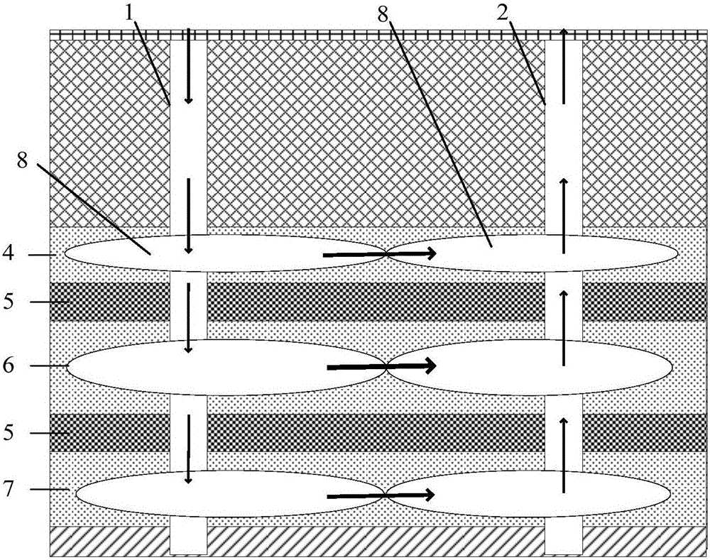
[0039] Such as figure 1 As shown, in the oil shale distribution area, the oil shale reservoir is 500m away from the surface. Oil shale reservoirs include layers of oil shale as well as layers of sandstone. Multiple layers of oil shale layers are stacked one after another in the vertical direction. In this embodiment, there are three oil shale layers, which are the bottom oil shale layer 7 , the middle oil shale layer 6 , and the top oil shale layer 4 from bottom to top. Each sandstone layer 5 is located between two adjacent oil shale layers, and the sandstone layer 5 separates the two adjacent oil shale layers. The oil shale layer is a thin interlayer. The thickness of a single layer of the oil shale layer is about 5m, the average oil content is as high as 13%, and the total water content is 4%. The exploitation of the oil and gas in the oil shale reservoir comprises the following steps:
[0040] In the oil shale distribution area, two open wells spaced apart from each oth...
Embodiment 2
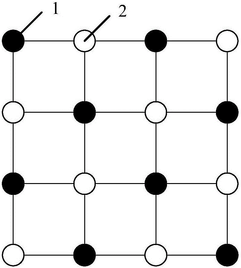
[0061] The difference between the exploitation method of the multi-layer thin interlayer oil shale in embodiment 2 and the exploitation method of multi-layer thin interlayer oil shale in embodiment 1 is that the oil shale distribution in embodiment 2 A plurality of first completion shafts 1 and a plurality of second completion shafts 2 are arranged in the area. For the sake of brevity, the following only introduces the positions of the plurality of first completion shafts 1 and the plurality of second completion shafts 2, and their beneficial effects.
[0062] image 3 It schematically shows the well pattern in which multiple first well completion wellbores 1 and multiple second well completion barrels are distributed. The well pattern is a checkerboard grid structure. A plurality of first completion wellbores 1 and a plurality of second completion wellbores 2 are evenly distributed in a matrix on the wellnet in the oil shale distribution area. The first completion shaft 1 ...
PUM
| Property | Measurement | Unit |
|---|---|---|
| Single layer thickness | aaaaa | aaaaa |
Abstract
Description
Claims
Application Information
 - R&D
- Intellectual Property
- Life Sciences
- Materials
- Tech Scout
- Unparalleled Data Quality
- Higher Quality Content
- 60% Fewer Hallucinations
Browse by: Latest US Patents, China's latest patents, Technical Efficacy Thesaurus, Application Domain, Technology Topic, Popular Technical Reports.
© 2025 PatSnap. All rights reserved.Legal|Privacy policy|Modern Slavery Act Transparency Statement|Sitemap|About US| Contact US: help@patsnap.com


