Water hammer shock wave impulse heat exchange device applied to ship water waste heat recovery system

A technology of waste heat recovery system and heat exchange device

Active Publication Date: 2017-01-11
常州贺斯特科技股份有限公司
6 Cites 5 Cited by

AI-Extracted Technical Summary

Problems solved by technology

However, due to the need to transport fluid through motors and frequency-regulated pipeline pumps, electric energy is required, and energy consumption is high
Traditional pulsation generators generally use e...

Abstract

The invention discloses a water hammer shock wave impulse heat exchange device applied to a ship water waste heat recovery system. The device comprises a plate heat exchanger; for one way of the plate heat exchanger, heat produced by a diesel engine cylinder sleeve water heat source is exchanged by the plate heat exchanger, circulating heat exchanging in the plate heat exchanger is realized through a first water pump, for the other way of the plate heat exchanger, a cooling medium is driven by a centrifugal water pump to flow through a flow adjusting valve and a shock valve on a main loop to enter the plate heat exchanger for heat absorbing, a three-way valve is arranged between the flow adjusting valve and the shock valve, one port of the three-way valve is connected with a spring check valve, the spring check valve is located in an energy storage tank, the energy storage tank is connected with the main loop through a branch pipeline, and heat removing equipment for cooling the heated cooling medium is arranged on the main loop. Impulses are produced in a main pipeline, the pulsatory cooling medium beats the inner wall of the plate heat exchanger, and the device has the advantages that the waste heat utilization efficiency is high, the size of the heat exchanger is small and the device is not prone to scaling.

Application Domain

Operating means/releasing devices for valvesCheck valves +3

Technology Topic

Shock waveCheck valve +10

Image

  • Water hammer shock wave impulse heat exchange device applied to ship water waste heat recovery system
  • Water hammer shock wave impulse heat exchange device applied to ship water waste heat recovery system
  • Water hammer shock wave impulse heat exchange device applied to ship water waste heat recovery system

Examples

  • Experimental program(1)

Example Embodiment

[0027] The present invention will be further described below in conjunction with the accompanying drawings.
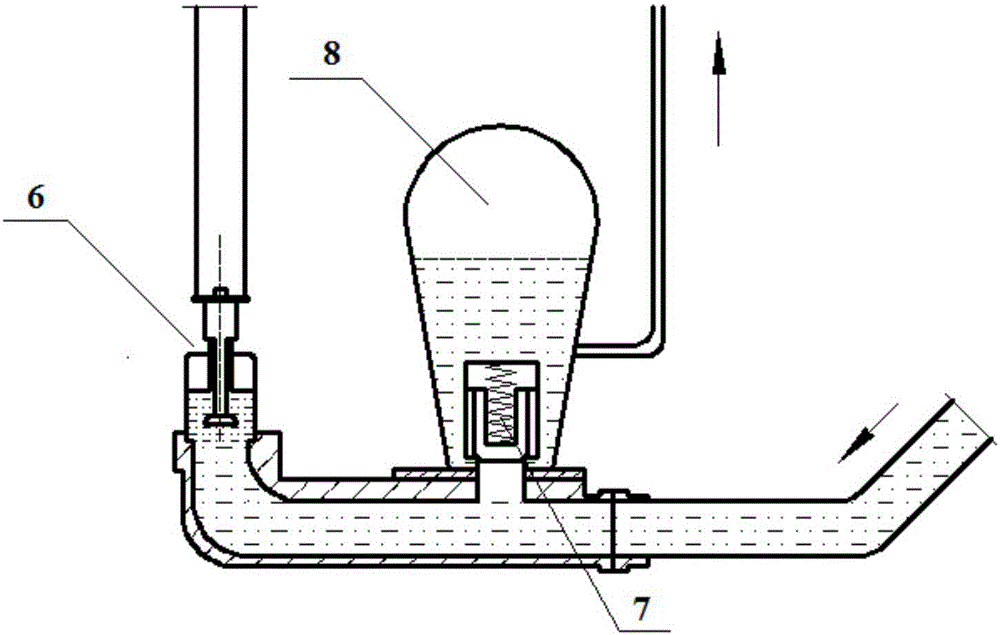
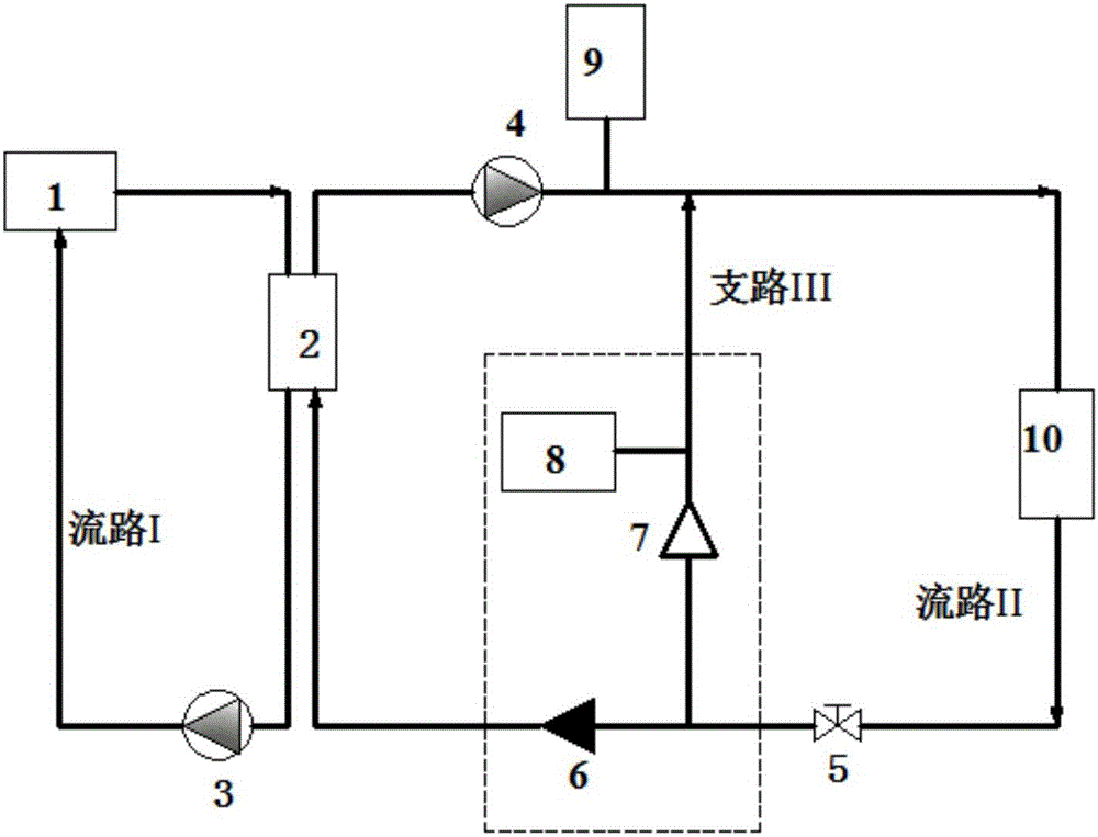
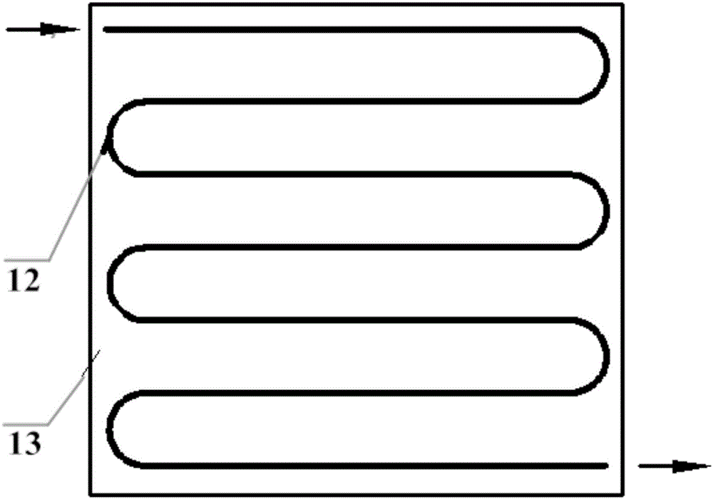
[0028]like Figure 1 to Figure 7 As shown in the figure, the water hammer shock wave pulsation heat exchange device applied to the ship water waste heat recovery system of the present invention includes a plate heat exchanger 2, and the plate heat exchanger 2 routes the heat generated by the diesel engine cylinder liner water heat source 1 through the plate heat exchanger. 2 heat exchange, circulating heat exchange in the plate heat exchanger 2 through the first water pump 3, and the other way through the centrifugal water pump 9 to drive the cooling medium to flow through the flow regulating valve 5 and the impact valve 6 set on the main circuit to enter the plate heat exchange. There is a three-way valve between the flow regulating valve 5 and the impact valve 6, and one port of the three-way valve is connected to the spring check valve 7, which is located in the energy storage tank 8, and the energy storage The tank material is stainless steel or plastic material, and the shape is a cuboid or a column. The energy storage tank 8 is connected to the main circuit through a branch pipeline, and the nozzle cross-sectional area of ​​the branch pipeline is smaller than that of the main circuit. There is a heat extraction device 10 for cooling the heated cooling medium, and a deaerator 4 is installed at the inlet of the plate heat exchanger 2 and the outlet of the heat extraction device 10 to prevent cavitation from damaging the device. The closing force of the valve body of the impact valve is less than the maximum impact force of the fluid, the closing force of the valve body of the spring one-way valve 7 is less than the maximum pulsating wave pressure generated, and the closing force of the spring one-way valve is 2 of the closing force of the impact valve. times.
[0029] In the present invention, the impact valve includes an inlet end, a steel valve body 63, a shaft 65, an impact washer 64, an O-ring 61, a nut 62 and an outlet end 66, and the steel valve body 63 is a cavity Structure, the steel valve body 63 is provided with an inlet end and an outlet end 66, a shaft 65 moving along the steel valve body is arranged in the steel valve body 63, and an O-ring 61 and an impactor are installed on the shaft 65. Gasket 64, the impact gasket 64 is fixed by the nut 62 installed on the shaft 65, the fluid flows in from the inlet end, when the fluid pressure is too large, the impact gasket 64 pushes upward to close the outlet end, and the fluid stops; when the fluid pressure gradually decreases When the fluid is small or the fluid flows back, the fluid force is not enough to overcome the weight of the impact washer 64 , and the impact washer 64 is separated from the O-ring 61 .
[0030] In the present invention, the spring one-way valve includes a steel spring valve body 73, a steel ball 72, and a spring 71. The steel spring valve body 73 is provided with an inlet and an outlet, and a steel ball 72 is provided at the inlet, and the steel ball 72 and the spring 71 are provided. One end of the spring 71 is mounted on the mounting plate 74, the mounting plate 74 is fixed in the cavity of the steel spring valve body 73, the mounting plate 74 is provided with a number of through holes, and the spring 71 acts to press the steel ball 72 against the steel ball 72. On the spring valve body 73, the pipeline between the one-way valve and the actuator is cut off. The fluid flows in from the inlet end, and a certain opening pressure is required to push the steel ball 72 to be able to open, and the fluid can flow; when the fluid pressure does not reach the opening force, stops working or the fluid returns, the spring 71 pushes the steel ball 72 to the inlet position to form Seal, play a non-return function.
[0031] In the present invention, the heat-extracting equipment 10 is a pan-type heating oil tank. The disk-type heating oil tank includes a coil heat exchanger 12 and an oil tank 13. The coil heat exchanger is communicated with the main circuit, and the pan The tube heat exchanger is located in the oil tank 13, and the coil heat exchanger is provided with an inlet fluid and an outlet fluid, the inlet fluid is the high temperature cooling medium after heat exchange, and the outlet fluid is the low temperature cooling medium after another heat exchange. The oil tank 13 can also be an absorption heat pump air conditioning system, heating, economizer and the like.
[0032] In the present invention, the closing force of the impact valve 6 is much smaller than the closing force of the spring check valve 7. When the flow rate of the cooling medium reaches a certain value, the impact valve 6 is closed due to water pressure, and a hydraulic impact is generated in the main circuit. After time, the impact force is enough to open the spring one-way valve 7, and its positive diffusion wave acts on the air chamber, causing pulsation, the pulse is transmitted to the main circuit through the branch pipe, and the pulsation is generated in the main circuit, waiting for its positive diffusion When the wave is consumed and transformed into a negative diffusion wave, the impact valve 6 is automatically opened to complete a cycle, reciprocating, and pulsation is generated in the plate heat exchanger 2, so that the heat exchange efficiency of the plate heat exchanger 2 is greatly improved. The high temperature water is transported to the heat extraction device 10 through the centrifugal water pump 9 .
[0033] The above is only the preferred embodiment of the present invention, it should be pointed out that: for those skilled in the art, without departing from the principle of the present invention, several improvements and modifications can also be made, and these improvements and modifications are also It should be regarded as the protection scope of the present invention.

PUM

no PUM

Description & Claims & Application Information

We can also present the details of the Description, Claims and Application information to help users get a comprehensive understanding of the technical details of the patent, such as background art, summary of invention, brief description of drawings, description of embodiments, and other original content. On the other hand, users can also determine the specific scope of protection of the technology through the list of claims; as well as understand the changes in the life cycle of the technology with the presentation of the patent timeline. Login to view more.

Similar technology patents

Geothermal energy collection pavement

InactiveCN113668320AImprove heat transfer performanceIncreased heat storage capacity
Owner:NEIJIANG NORMAL UNIV

Intelligent self-adaptive fin, fin module and application thereof to solar unmanned aerial vehicle

ActiveCN111336854AImprove heat transfer performanceIncrease heat exchange rate
Owner:NORTHWESTERN POLYTECHNICAL UNIV

Combined heat exchanger

ActiveCN104676976AImprove heat transfer performanceImprove heat exchange efficiency
Owner:烟台施泰普节能技术有限公司

Welding method for secondary degassing sealing of ultrathin vapor chamber

PendingCN113084348AImprove heat transfer performanceReduce processing costs
Owner:SOUTH CHINA UNIV OF TECH

Motor stator structure based on liquid metal encapsulation

PendingCN114567124AImprove heat transfer performanceReduce thermal resistance
Owner:INST OF ELECTRICAL ENG CHINESE ACAD OF SCI

Classification and recommendation of technical efficacy words

  • Improve heat transfer performance
  • save space

Anti-corrosion heat-conducting coating for heat exchanger and preparation method of coating

ActiveCN102964963Ahigh thermal conductivityImprove heat transfer performance
Owner:江苏四方威凯科技有限公司

Heat exchange fin and heat exchanger

InactiveCN104596343AIncrease the heat exchange areaImprove heat transfer performance
Owner:HISENSE HOME APPLIANCES GRP CO LTD +1

Heat transfer process for variable cross section intensive selfoscillatory flow heat pipe

InactiveCN1632441AImprove heat transfer performanceHigh heat transfer efficiency
Owner:NORTH CHINA ELECTRIC POWER UNIV (BAODING)

Fabricated tube for an evaporator

InactiveUS20110284195A1improve heat transfer performanceincrease robustness
Owner:MAHLE INT GMBH

Air guiding structure of air conditioner, air pipe machine and air conditioner

InactiveCN105180398AImprove air flowImprove heat transfer performance
Owner:GREE ELECTRIC APPLIANCES INC OF ZHUHAI

Multi-node management method and system

Owner:XFUSION DIGITAL TECH CO LTD

Chemiluminescence immunoassay device

InactiveCN104777321Asave spaceHigh detection throughput
Owner:TSINGHUA UNIV +1

Protective frame for mobile communication device

InactiveUS20130088815A1minimize size and weightsave space
Owner:TAER INNOVATION

Folding type aerial photography aircraft

InactiveCN105035303Areduce volumesave space
Owner:WUXI MIRACLE SCI & TECH CO LTD
Why Eureka
Try Eureka