Electronic delay magneto electric detonator controller and control method thereof

A controller and detonator technology, used in electric fuzes, weapon accessories, fuzes, etc., can solve the problems of complex production process, poor safety in production links, hidden dangers, etc., and achieve high delay accuracy, improved reliability and online detection functions. Effect

Inactive Publication Date: 2017-01-11
沈阳三阳电子标签有限公司
View PDF5 Cites 4 Cited by
  • Summary
  • Abstract
  • Description
  • Claims
  • Application Information

AI Technical Summary

Problems solved by technology

[0002] At present, the traditional magnetoelectric detonator still has the following disadvantages in the process of use: the bus bar of the traditional magnetoelectric detonator passes through the detonation network formed by the magnetic ring in turn, and the secondary legs of each magnetoelectric detonator are subjected to the current The limit of some detonating devices is generally only more than two meters long, which is greatly restricted in medium and deep hole blasting operations such as metal mines and deep wells.
The delay function of the magnetoelectric detonator is still the method of drug delay. Although the principle of drug delay is simple, the production process is complicated, the safety of the production process is poor, and the delay body is prone to rapid detonation due to the unevenness of the drug, and the product performance is consistent. sex is also poor
The currently used magnetoelectric detonators use instant ignition to detonate the detonators, and there is no password verification function, which has great potential safety hazards in the management, circulation and use of magnetoelectric mines.

Method used


Image

  • Electronic delay magneto electric detonator controller and control method thereof
  • Electronic delay magneto electric detonator controller and control method thereof
  • Electronic delay magneto electric detonator controller and control method thereof

Examples


Embodiment Construction

[0022] The present invention will be further described below in conjunction with the examples. The following examples are only several specific embodiments of the present invention, but the design concept of the present invention is not limited thereto, and any non-substantial changes to the present invention by using this concept should belong to the act of violating the protection scope of the present invention.

[0023] The following circuits are conventional circuits in this field unless otherwise specified.

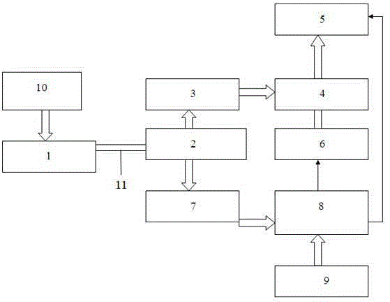
[0024] Such as figure 1 As shown, the electronic delay magnetoelectric detonator controller of the present invention has the following structure: the signal output end of the detonator 10 is connected with the input end of the electromagnetic electric energy conversion unit 1, and the electromagnetic electric energy conversion unit 1 is connected to the thunderbolt through the detonator foot wire 11. The pin line polarity judgment unit 2 is connected, the output en...


PUM


Abstract

The invention discloses a magneto electric detonator controller, and especially relates to an electronic delay magneto electric detonator controller and a control method thereof. According to the electronic delay magneto electric detonator controller, the signal output end of a special magneto electric exploder is connected with the input end of an electromagnetism electrical energy converting unit; the electromagnetism electrical energy converting unit is connected with a detonator leg wire polarity judging unit through a detonator leg wire; the output end of the detonator leg wire polarity judging unit is connected with a rectifying and voltagestabilizing circuit and a data communication input unit; the output end of the data communication input unit is connected with a center processor; the output end of a rectification and voltagestabilizing circuit is connected with an electric energy storage circuit; the electric energy storage circuit and the center processor are connected with an energy storage element discharge circuit; the output end of the center processor is connected with a detonator firing circuit. The electronic delay magneto electric detonator controller has the relatively good functions of stray electricity resistance, static electricity resistance, and radio-frequency radiation resistance, has high delay time accuracy, simplifies the production technology, and improves the detonator safety in use.

Description

technical field [0001] The invention relates to a magnetoelectric detonator controller, in particular to an electronic device capable of converting alternating electric energy into magnetic energy, efficiently reducing magnetic energy into electric energy through electromagnetic coupling, and completing two-wire non-polarity data communication and providing electric energy. Delayed magneto-electric detonator controller. Background technique [0002] At present, the traditional magnetoelectric detonator still has the following disadvantages in the process of use: the bus bar of the traditional magnetoelectric detonator passes through the detonation network formed by the magnetic ring in turn, and the secondary legs of each magnetoelectric detonator are subjected to the current The limitation of some detonating devices is generally only more than two meters long, which is greatly restricted when medium and deep hole blasting operations such as metal mines and deep wells. With...

Claims


Application Information

Patent Timeline
Patent Type & Authority Applications(China)
IPC IPC(8): F42C19/12F42C11/06
Inventor 马晓明朱俊英
Owner 沈阳三阳电子标签有限公司
Why Eureka
Try Eureka