A time-delay optical fiber and reference optical fiber packaging structure for optical fiber hydrophone modulation system

A technology of optical fiber hydrophone and reference optical fiber, which is applied in the direction of instruments, installation, optics, etc., can solve the problems of high working temperature, affecting the working accuracy of the system, affecting the normal working state of the optical fiber, etc., to eliminate adverse effects and improve The effect of space utilization

Active Publication Date: 2020-07-14
BEIJING INST OF AEROSPACE CONTROL DEVICES
View PDF6 Cites 0 Cited by
  • Summary
  • Abstract
  • Description
  • Claims
  • Application Information

AI Technical Summary

Problems solved by technology

Because the same type of polarization-maintaining fiber is used for the reference optical fiber, the delay optical fiber and the sensitive optical fiber, all the optical fibers are sensitive to the sound pressure signal, but there is no need for the reference optical fiber and the delayed optical fiber to respond to the sound pressure signal; at the same time, because The thermal expansion of the material and the optical fiber have high requirements on the working temperature. The change of the light environment temperature will cause the change of the corresponding performance of the optical fiber, and will also greatly affect the working accuracy of the system. In addition, the optical fiber hydrophone modulation system in the complex working environment, will Affected by vibration, it affects the normal working state of the optical fiber and the quality of optical signal transmission

Method used


Image

  • A time-delay optical fiber and reference optical fiber packaging structure for optical fiber hydrophone modulation system
  • A time-delay optical fiber and reference optical fiber packaging structure for optical fiber hydrophone modulation system
  • A time-delay optical fiber and reference optical fiber packaging structure for optical fiber hydrophone modulation system

Examples


Embodiment Construction

[0032] The present invention will be further described below in conjunction with the accompanying drawings.

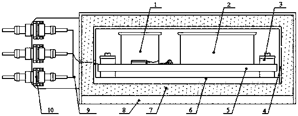
[0033] Such as figure 1 As shown, the present invention proposes a time-delay optical fiber and a reference optical fiber packaging structure for an optical fiber hydrophone modulation system, including a reference optical fiber winding column 1, a time-delay optical fiber winding column 2, a vibration isolation structure 3, and an inner layer Protective cover 4, inner mounting base plate 5, middle mounting base plate 6, sound and heat insulation filling structure 7, outer mounting base plate 8, outer protective cover 9, optical fiber connection flange assembly 10,

[0034] The reference fiber winding column 1 and the time-delay fiber winding column 2 are installed on the inner mounting base plate 5, the middle mounting base plate 6 is placed under the inner mounting base plate 5, and the middle mounting base plate 6 is connected to the inner layer mounting base plate ...


PUM

PropertyMeasurementUnit
thicknessaaaaaaaaaa
Resonant frequencyaaaaaaaaaa
Sound absorption coefficientaaaaaaaaaa

Abstract

The invention discloses a time-delay optical fiber and reference optical fiber encapsulation structure for an optical fiber hydrophone modulation system. The sound absorption coefficient of the sound insulation and thermal insulation filling structure of the time-delay optical fiber and reference optical fiber encapsulation structure of the invention is not smaller than 0.75; the internal noise of the encapsulation structure which has been subjected to sound insulation is not larger than 25dB; and the disturbance of external sound signals and temperature can be effectively insulated. According to the time-delay optical fiber and reference optical fiber encapsulation structure of the invention, SE series damping silicone rubber is adopted to make vibration isolation gaskets; a four-point support arrangement mode is adopted; and with the vibration isolation structures adopted, vibration above 20HZ transferred to an inner-layer mounting bottom plate from a middle-layer mounting bottom plate can be blocked, and vibration decrease efficiency is greater than 85%, and adverse effects on an optical path caused by external vibration can be effectively eliminated.

Description

technical field [0001] The invention relates to a time-delay optical fiber and a reference optical fiber packaging structure used in an optical fiber hydrophone modulation system, and belongs to the field of optical fiber hydrophone modulation systems. Background technique [0002] Optical fiber hydrophone is a new type of aquatic signal detection sensor based on optical fiber sensing technology. Its principle is to use sound waves to modulate the intensity, polarization, phase and other parameters of light waves to obtain information such as frequency and intensity of sound waves. The advantage of the optical fiber hydrophone is that the buried communication optical cable can be used as a sensing medium and a data communication medium at the same time, and no power supply is required throughout the process. It has significant advantages over traditional piezoelectric hydrophones in terms of sensitivity, frequency band, and anti-electromagnetic interference. In recent years...

Claims


Application Information

Patent Timeline
Patent Type & Authority Patents(China)
IPC IPC(8): G01H3/00G01H9/00G02B7/00
CPCG01H3/00G01H9/004G02B7/00
Inventor 侯振兴于文鹏张磊郑百超李振郝良彬张海岩王海亮
Owner BEIJING INST OF AEROSPACE CONTROL DEVICES
Why Eureka
Try Eureka