Triaxial decoupling self-zero-setting fluxgate magnetometer zero point measurement circuit

A technology for measuring circuits and magnetometers, which is used in the measurement of electrical variables, measuring devices, instruments, etc., and can solve the problem of unstable working state of the magnetometer probe core, serious circuit zero temperature drift and time drift, and time and temperature effects. Large and other problems, to achieve the effect of improving energy utilization efficiency, low zero point stability, and improving zero point stability

Active Publication Date: 2017-01-11
NAVAL UNIV OF ENG PLA
5 Cites 5 Cited by

AI-Extracted Technical Summary

Problems solved by technology

In order to reduce the power consumption of the magnetometer to the milliwatt level, the excitation waveform with a narrow pulse width is often used; the working state of the magnetometer probe core is unstable and is greatly affected by time and temperature, making the output of the magnetometer ...

Method used

Fig. 4 is the matching schematic diagram of zero-point measurement control circuit and other components in the embodiment; Its zero-point measurement control circuit comprises two groups of switches; Under the control of micro-processing unit, switch by two groups of switches to make the two groups of probe signal coils The output terminal is reversed, the output voltage value before and after the reverse is measured, and the zero point of the circuit is obtained according to the output voltage value; this zero point measurement method can be accurately carried out online and eliminated, reducing the influence of zero point drift on the measurement results.
Fig. 5 is the schematic diagram of three-axis fluxgate weak coupling installation mode in the embodiment; Wherein, three-axis probes are orthogonal and three-axis probes each have a symmetry axis on a straight line; Wherein two-axis probes are not coplanar positive Intersect, and be perpendicular to the line connecting the midpoints of the cores of the two-axis probes, and the other axis probe is installed on the extension line of the line connecting the midpoints of the cores of the two-axis probes. This installation method ensures that the feedback magnetic field and excitation magnetic field of any axis in the magnetometer have little influence on other axes, thereby reducing the three-axis coupling error.
For improving the precision and the resolution of three-axis fluxgate magnetometer, and long-term zero stability; Adopt the intermitten...

Abstract

The invention discloses a triaxial decoupling self-zero-setting fluxgate magnetometer zero point measurement circuit, and the circuit employs a bipolar intermittent pulse excitation unit composed of low-power-consumption temperature control crystal oscillator to carry out the excitation of an iron core. The circuit employs the temperature control crystal oscillator to stabilize the work frequency, enables the iron core to be demagnetized in real time in a mode of bipolar excitation, and employs an intermittent pulse voltage excitation waveform to greatly reduce the power consumption. The circuit controls a constant voltage source to carry out the excitation of the iron core through a low-resistance switch, and greatly improves the energy utilization efficiency of the excitation unit. The circuit provided by the invention employs a weak coupling mode to install a triaxial magnetic probe, reduces the triaxial coupling error through the optimization of the relative position of the triaxial magnetic probe, employs a zero point automatic measurement circuit, can carry out the programming control to achieve the online detection of a circuit zero point, and can be used in the fields of magnetic field measurement and magnetic object detection.

Application Domain

Electrical measurements

Technology Topic

PhysicsConstant voltage +11

Image

  • Triaxial decoupling self-zero-setting fluxgate magnetometer zero point measurement circuit
  • Triaxial decoupling self-zero-setting fluxgate magnetometer zero point measurement circuit
  • Triaxial decoupling self-zero-setting fluxgate magnetometer zero point measurement circuit

Examples

  • Experimental program(1)

Example Embodiment

[0030] In order to make the objectives, technical solutions, and advantages of the present invention clearer, the following further describes the present invention in detail with reference to the accompanying drawings and embodiments. It should be understood that the specific embodiments described herein are only used to explain the present invention, but not to limit the present invention. In addition, the technical features involved in the various embodiments of the present invention described below can be combined with each other as long as they do not conflict with each other.
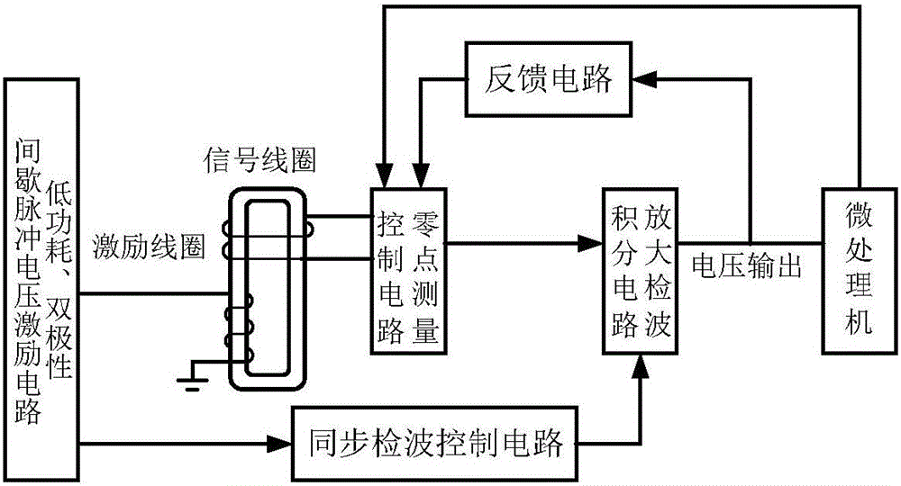
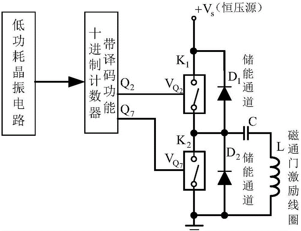
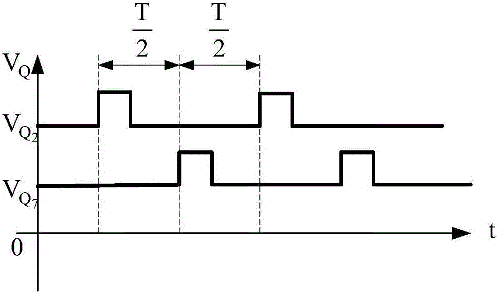
[0031] The power consumption of the fluxgate magnetometer is mainly distributed in the excitation unit, the amplifying detection integration circuit and the feedback circuit; the key to reducing the detection power consumption of the fluxgate magnetometer is to reduce the power consumption of the excitation unit; the present invention reduces the excitation power consumption The specific measure is to use the bipolar intermittent pulse voltage excitation method, with a narrow rectangular pulse, through a low on-resistance switch, control a constant voltage source to excite the fluxgate iron core, and the iron core is periodically excited to saturation Status, to ensure that the magnetometer has sufficient resolution, while greatly improving the energy utilization efficiency of the excitation unit.
[0032] figure 1 Shown is a functional block diagram of the first axis zero point measurement circuit of the low-power three-axis decoupling self-zeroing fluxgate magnetometer provided by the embodiment; including an excitation unit, an excitation coil, a signal coil, a feedback circuit, and a zero point measurement The control circuit, synchronous detection control circuit, amplification detection integration circuit and micro-processing unit; the zero point measurement circuit of the remaining two axes is the same.
[0033] figure 2 Shown is a schematic diagram of the excitation unit in the embodiment; in the embodiment, the excitation unit includes a square wave signal generating unit, a counting decoding circuit, a first energy storage unit and a second energy storage unit;
[0034] Wherein, the input terminal of the counting and decoding circuit is connected with the output terminal of the square wave signal generating unit; the first terminal of the first energy storage unit is connected with the first output terminal of the counting and decoding circuit, and the power terminal is used to connect an external constant voltage source ;
[0035] The first end of the second energy storage unit is connected to the second output end of the counting and decoding circuit, the second end is connected to the second end of the first energy storage unit, the third end is connected to the third end of the first energy storage unit, The fourth end is grounded, and the fifth end is connected to the excitation coil.
[0036] image 3 As shown, it is a schematic diagram of the excitation waveform generated by the excitation unit in the embodiment; during the high level of the excitation pulse Q2, the switch K1 of the first energy storage unit is turned on, and the switch K2 of the second energy storage unit is turned off. The on-resistance is much smaller than the excitation coil impedance, and the voltage across the switch can be ignored; the reverse voltage charged on the capacitor C of the second energy storage unit and most of the power supply voltage Vs fall on both ends of the excitation coil, and the energy utilization rate Very high; the excitation unit slowly increases the excitation current with a stable voltage amplitude to drive the iron core to saturation to ensure that the magnetometer has a strong enough signal output;
[0037] When the fluxgate core is excited to saturation, the instantaneous inductance L of the excitation coil is small, the excitation current increases rapidly, and the capacitor is quickly charged. After a period of time, the capacitor is charged to close to the power supply voltage, so that the voltage across the excitation coil is very high. Small, the excitation current no longer increases, limiting the saturation depth of the iron core and reducing power consumption;
[0038] When the excitation pulse Q2 turns to a low level, the switch K1 of the first energy storage unit is turned off, and the excitation coil loop current continues to charge the capacitor C through the diode D2 under the action of inertial inertia, and the remaining energy on the excitation coil inductance is stored in the capacitor on;
[0039] In the second half of the excitation cycle, during the high level of pulse Q7, the switch K2 of the second energy storage unit is turned on, the switch K1 of the first energy storage unit is turned off, and the voltage stored on the capacitor C is applied to both ends of the excitation coil , Reverse excitation of the fluxgate core, the time waveform of the excitation voltage is basically symmetrical with the first half cycle, and the magnetometer has similar signal output with the first half cycle;
[0040] When the excitation pulse Q7 turns to a low level, the switch K2 of the second energy storage unit is turned off, and the excitation coil loop current continues to charge the capacitor C through the diode D1 under the action of inertial inertia, and the remaining energy in the excitation coil inductance is also Stored on the capacitor;
[0041] During the entire excitation cycle, only when Q2 is at high level, can the power supply supplement the excitation energy, and the pulse width of Q2 is very narrow, so the energy consumption is very low; moreover, through the energy storage of the diode, the flux gate will be ironed every time After the core is excited to saturation, the remaining energy in the excitation coil inductance L is converted into capacitor energy and stored, so that the energy consumed in each excitation cycle is mainly the core hysteresis loss and the heat loss on the coil internal resistance. Therefore, The excitation unit in the embodiment has a high energy utilization rate, and the average power supply current of the circuit can be conveniently controlled below 0.3 mA.
[0042] In order to improve the accuracy and resolution of the three-axis fluxgate magnetometer, as well as the long-term zero point stability; in the embodiment, a temperature-controlled crystal oscillator circuit with high stability and low power consumption is used to generate intermittent pulse voltage waveforms with stable frequency and width, and pass low Resistance switch, turn on the constant voltage source to excite the iron core, the excitation signal waveform is positive and negative, and the frequency, width, and amplitude are all stable measures, thus ensuring the stability of the magnetometer zero point; and, due to the high excitation energy utilization rate, Under the condition of low power consumption, the iron core can still be excited to deep saturation, which ensures the stability and high resolution of the magnetometer.
[0043] Figure 4 It is a schematic diagram of the matching of the zero point measurement control circuit and other components in the embodiment; the zero point measurement control circuit includes two sets of switches; under the control of the micro-processing unit, the two output ends of the probe signal coil are switched to reverse , Measure the output voltage value backwards and backwards, and obtain the zero point of the circuit according to the output voltage value; this zero point measurement method can be accurately performed on-line and eliminated, which reduces the impact of zero point drift on the measurement results.
[0044] Figure 5 It is a schematic diagram of the three-axis fluxgate weak coupling installation method in the embodiment; among them, the three-axis probe is orthogonal and the three-axis probe has a symmetry axis on a straight line; the two-axis probe is not coplanar and orthogonal to this The line connecting the center points of the two-axis probe cores is vertical, and the other axis probe is installed on the extension line of the line connecting the center points of the first two-axis probe cores. This installation method ensures that the feedback magnetic field and excitation magnetic field of any axis in the magnetometer have little effect on other axes, thereby reducing the three-axis coupling error.
[0045] Those skilled in the art can easily understand that the above descriptions are only preferred embodiments of the present invention and are not intended to limit the present invention. Any modification, equivalent replacement and improvement, etc. made within the spirit and principle of the present invention, All should be included in the protection scope of the present invention.

PUM

no PUM

Description & Claims & Application Information

We can also present the details of the Description, Claims and Application information to help users get a comprehensive understanding of the technical details of the patent, such as background art, summary of invention, brief description of drawings, description of embodiments, and other original content. On the other hand, users can also determine the specific scope of protection of the technology through the list of claims; as well as understand the changes in the life cycle of the technology with the presentation of the patent timeline. Login to view more.

Similar technology patents

Method for synthesizing cyclic carbonate ester in micro reactor system

ActiveCN102464521AImprove energy efficiencyfast reaction rate
Owner:DALIAN INST OF CHEM PHYSICS CHINESE ACAD OF SCI

Classification and recommendation of technical efficacy words

  • Improve energy efficiency

Heat Transfer compositions

InactiveUS20090158771A1contribution be reduceimprove energy efficiency
Owner:INEOS FLUOR HLDG

Vehicle control apparatus

InactiveUS6930405B2improve energy efficiencyrecover kinetic energy
Owner:NISSAN MOTOR CO LTD

Safe power utilization management system and method based on edge calculation and big data analysis

InactiveCN111062651AReduce electrical safety risksImprove energy efficiency
Owner:南京中电科能技术有限公司

Data center energy saving system and method based on virtual IT resource distribution technology

ActiveCN103345298AImprove stability and longevityImprove energy efficiency
Owner:SHANDONG COMP SCI CENTNAT SUPERCOMP CENT IN JINAN
Why Eureka
Try Eureka