Model for calculating iron loss of improved switched reluctance motor

A switched reluctance motor and calculation model technology, which is applied in calculation, electrical digital data processing, design optimization/simulation, etc., can solve the problems of large fitting error, inapplicability, and large calculation error

Active Publication Date: 2017-01-11
CHINA UNIV OF MINING & TECH
View PDF2 Cites 16 Cited by
  • Summary
  • Abstract
  • Description
  • Claims
  • Application Information

AI Technical Summary

Problems solved by technology

At present, there are mainly two types of loss calculation models for switched reluctance motors. One is the binomial calculation model established according to the classic Steinmetz formula, combined with the iron loss data of ferromagnetic materials used in the motor, and the hysteresis loss coefficient is obtained by fitting according to the Steinmetz formula , eddy current loss coefficient and Steinmetz factor, and then establish the iron loss calculation model of the motor; secondly, according to the trinomial calculation model proposed by Bertotti considering the abnormal loss, the hysteresis loss coefficient, eddy current loss coefficient and abnormal loss coefficient are obtained by fitting, Finally, the iron loss calculation model of the motor is established; the above models are all coefficients determined under the condition of fixed frequency, and the coefficients determined above are constants, and the fitting error is relatively large. If it is not fixed, the calculation error is large, so it is not suitable

Method used


Image

  • Model for calculating iron loss of improved switched reluctance motor
  • Model for calculating iron loss of improved switched reluctance motor
  • Model for calculating iron loss of improved switched reluctance motor

Examples


Embodiment Construction

[0036] An embodiment of the present invention will be further described below in conjunction with the accompanying drawings.

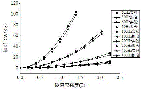
[0037] When the magnetic field is a sinusoidal alternating magnetic field, the peak value of the magnetic induction intensity is close to saturation, and the influence of the skin effect on the eddy current at high frequencies is ignored, the expression of the Steinmetz iron loss calculation model is:

[0038] P fe =k h f α +k e f 2 B 2 (1)

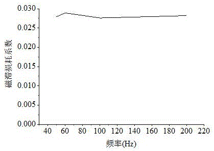
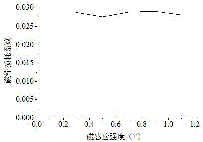
[0039] In the formula, B is the magnetic induction intensity, f is the frequency, k h B α f is hysteresis loss, k e B 2 f 2 is the eddy current loss, k h 、k e and α are hysteresis loss coefficient, eddy current loss coefficient and Steinmetz factor respectively, and their values ​​directly affect the accuracy of the calculation model.

[0040] order k h Bα =C,k e B 2 =D, and divide the left and right sides by f to get

[0041] P f e ...


PUM


Abstract

The invention discloses a model for calculating the iron loss of a switched reluctance motor, and belongs to the technical field of the calculation and analysis of the iron loss of the switched reluctance motor. The model is a variable coefficient binomial calculation model; according to the model, by conducting the data analysis of the actually measured loss value of a ferromagnetic material under the conditions of different frequency and magnetic field intensity, the laws of a few key parameters such as hysteresis loss coefficient and eddy current loss coefficient varying with the magnetic induction intensity and frequency can be obtained, thus the iron loss of the ferromagnetic material at the time of sinusoidal alternating magnetization can be calculated. According to the magnetic induction intensity waveform non-sinusoidal special situation in the switched reluctance motor, the finite element method calculation is applied to obtain the waveforms of the tangential direction and radial direction magnetic induction intensity, changing with time, of each part of a motor, the Fourier decomposition is applied to decompose an non-sinusoidal magnetic induction intensity waveform into a list of sinusoidal waveforms, the variable coefficient binomial calculation model is adopted to calculate the iron loss of harmonic waves in each time, then the accumulation and summation is conducted so as to obtain a harmonic wave unit quality iron loss model after accumulating for (i)n(/i) times.

Description

technical field [0001] The invention relates to an improved calculation model for iron loss of switched reluctance motors, which is especially suitable for switched reluctance motors with various phase numbers and structures. Background technique [0002] The switched reluctance motor has the advantages of simple structure, sturdy and durable, reliable operation, and high energy conversion efficiency. It is difficult to calculate the iron loss of the switched reluctance motor. To find out the mechanism of the iron loss of the switched reluctance motor can find the theoretical basis and improvement direction for improving the working efficiency of the motor; when establishing the motor control system model, it can be considered to include the iron loss, so as to get more Accurate system control model; it is also very helpful for choosing a suitable heat dissipation method and prolonging the applicable life of the motor. Therefore, it is a difficult problem to study an accura...

Claims


Application Information

Patent Timeline
Patent Type & Authority Applications(China)
IPC IPC(8): G06F17/50
CPCG06F30/20
Inventor 陈昊闫文举刘征李冬
Owner CHINA UNIV OF MINING & TECH
Why Eureka
Try Eureka