Permanent magnet synchronous rotation elimination motor of rotation elimination platform

A permanent magnet synchronous and derotation platform technology, applied to synchronous motors with stationary armatures and rotating magnets, synchronous machine parts, etc., can solve the problems of large volume and weight, low energy density, and reduce system weight. Achieve the effects of small size, low moment of inertia, and structural safety

Inactive Publication Date: 2017-01-11
上海航天智能装备有限公司
View PDF8 Cites 0 Cited by
  • Summary
  • Abstract
  • Description
  • Claims
  • Application Information

AI Technical Summary

Problems solved by technology

The number of pole slots in this patent is relatively small, and there is a defect of low energy density, and the patent has a large volume and weight, which is not conducive to reducing the weight of the entire system

Method used


Image

  • Permanent magnet synchronous rotation elimination motor of rotation elimination platform
  • Permanent magnet synchronous rotation elimination motor of rotation elimination platform
  • Permanent magnet synchronous rotation elimination motor of rotation elimination platform

Examples


Embodiment 1

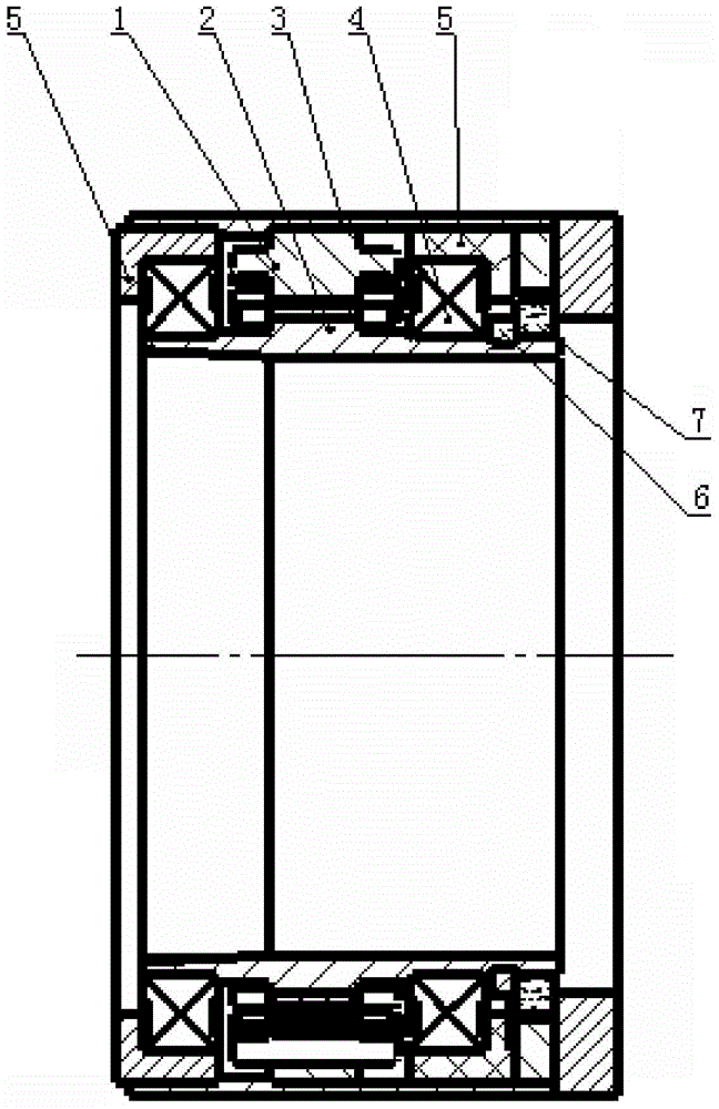
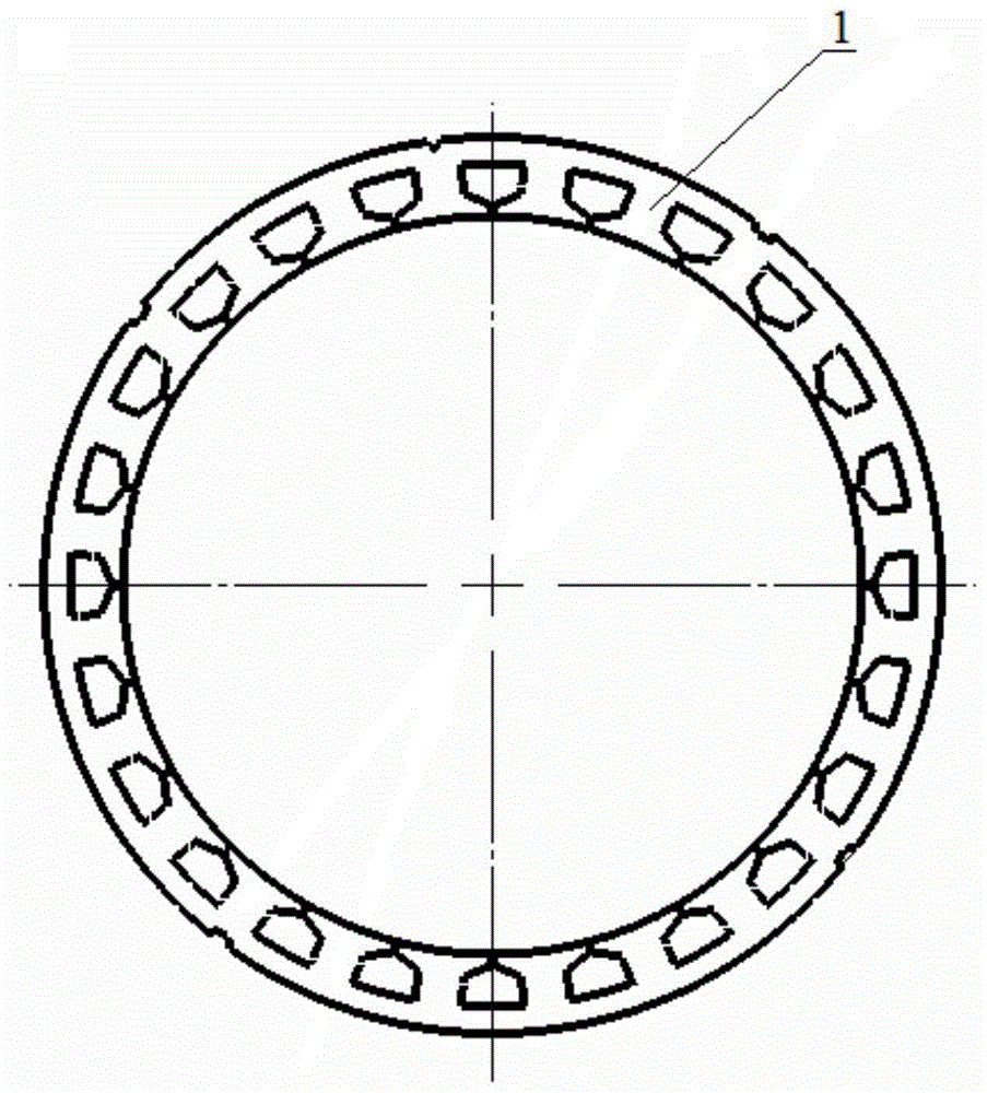
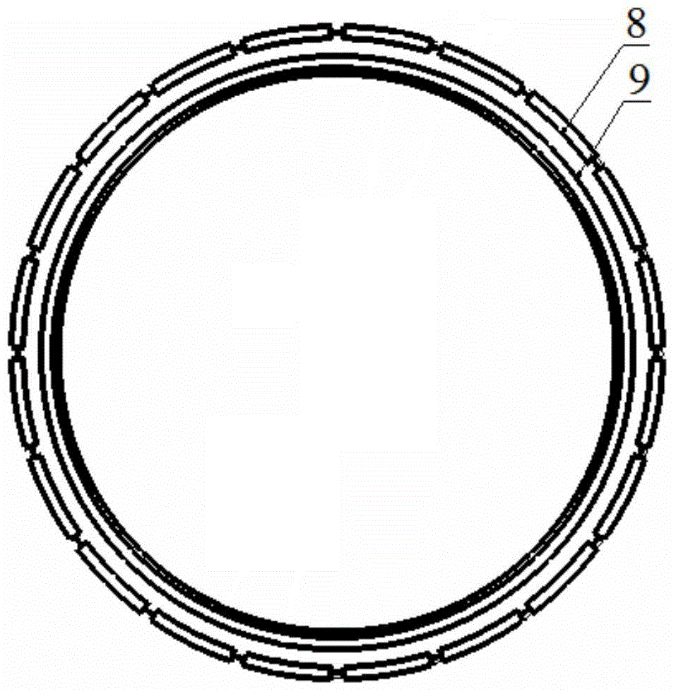
[0031] Such as figure 1 As shown, a permanent magnet synchronous derotation motor of a derotation platform includes a casing 3, a stator 1 and a rotor 2 arranged sequentially from outside to inside, a position sensor 7 and a wire retaining ring 6, and the rotor 2 is connected to the machine through a bearing 4. The casing 3 is connected, the bushing 5 is provided between the bearing 4 and the casing 3, end covers are provided at both ends of the casing 3, the stator 1 includes a stator core and a stator winding, and the stator winding is connected to a servo motor driver, such as figure 2 As shown, the inner circumference of the stator 1 is a circular multi-slot structure, and the rotor 2 is a surface-mounted structure with near-pole slots, as shown in image 3 As shown, it includes a rotor core 9 and a permanent magnet 8. The rotor core 9 is a ring structure and serves as a rotating shaft. A plurality of protruding rotor teeth are evenly distributed on the outer surface of t...

Embodiment 2

[0036] The difference between this embodiment and Embodiment 1 is that the number of slots in the stator 1 is 22, and the rotor 2 is used to achieve high energy density of the motor. The permanent magnet 8 has 18 poles, and the stator 1 is used to realize the motor to spin up quickly and rotate within 0.06s. Reach 780r / min, all the other structures are with embodiment one.

Embodiment 3

[0038] The difference between this embodiment and Embodiment 1 is that the number of slots in the stator 1 is 26, and the rotor 2 is used to achieve high energy density of the motor. The permanent magnet 8 has 22 poles, and the stator 1 is used to realize the motor to spin up quickly and rotate within 0.06s. Reach 780r / min, all the other structures are with embodiment one.


PUM


Abstract

The invention relates to a permanent magnet synchronous rotation elimination motor of a rotation elimination platform. The permanent magnet synchronous rotation elimination motor comprises a machine shell, a stator and a rotor which are arranged from outside to inside in sequence, wherein the rotor is connected with the machine shell through a bearing; the stator is connected with a servo motor driver; the inner circumference of the stator adopts a regularly-round multi-groove structure; the rotor adopts a near-polar-slot surface-mounted type structure; the rotor comprises a rotor iron core and permanent magnets; the rotor iron core adopts an annular structure; multiple convex rotor teeth are uniformly distributed on the outer surface of the rotor iron core; the permanent magnets are fixed between adjacent rotor teeth; and the permanent magnets are cuboid-shaped magnetic steel or arc-shaped magnetic steel with equal thickness in each place. Compared with the prior art, the permanent magnet synchronous rotation elimination motor has the advantages of simple structure, light weight, low rotational inertia, high efficiency, high power density, short end part winding, relatively high flux-weakening capability and the like, and is applicable to motor structure design of specific dimensions in the rotation elimination platform; and meanwhile, the speed of the permanent magnet synchronous rotation elimination motor can reach 780r/min within 0.06s.

Description

technical field [0001] The invention relates to a permanent magnet synchronous motor, in particular to a permanent magnet synchronous derotation motor of a derotation platform. Background technique [0002] For a rotating missile, the missile body rotates around its longitudinal axis at a high speed, causing kinematic coupling to the attitude of the inertial platform and antenna. The derotation platform system can isolate the coupling effect of the projectile motion on the inertial platform, maintain the stability of the antenna in the inertial space, and improve the missile guidance accuracy. The change law of the rotation speed of the rotating missile is generally that it increases rapidly when it is launched, then decreases, and finally rises to a certain value and then stabilizes. The time interval between launching and stabilizing the rotational speed of the rotating missile is very short, only a few seconds. Therefore, the derotation motor as the driving component in ...

Claims


Application Information

Patent Timeline
Patent Type & Authority Applications(China)
IPC IPC(8): H02K21/16H02K21/02
Inventor 蒋燕飞
Owner 上海航天智能装备有限公司
Why Eureka
Try Eureka