Friction welding machine and spindle force balancing assembly thereof

A friction welding and force balance technology, applied in welding equipment, non-electric welding equipment, metal processing equipment, etc., can solve problems such as low service life

Inactive Publication Date: 2017-01-18
CHONGQING TURBO FLOW MACHINERY MFG
View PDF10 Cites 3 Cited by
  • Summary
  • Abstract
  • Description
  • Claims
  • Application Information

AI Technical Summary

Problems solved by technology

Obviously, the maximum bearing capacity of the main shaft bearing determines the welding capacity of the entire friction welding machine. In addition, the long-term bearing of the huge axial force of the main shaft bearing also makes its service life shorter

Method used


Image

  • Friction welding machine and spindle force balancing assembly thereof

Examples


Embodiment Construction

[0021] One of the cores of the present invention is to provide a spindle force balance assembly of a friction welding machine, so as to improve the processing capacity of the friction welding machine on the one hand, and to increase the service life of the spindle bearing on the other hand.

[0022] Another core of the present invention is to provide a friction welding machine with the above-mentioned spindle force balance assembly.

[0023] In order to enable those skilled in the art to better understand the solution of the present invention, the present invention will be further described in detail below in conjunction with the accompanying drawings and specific embodiments.

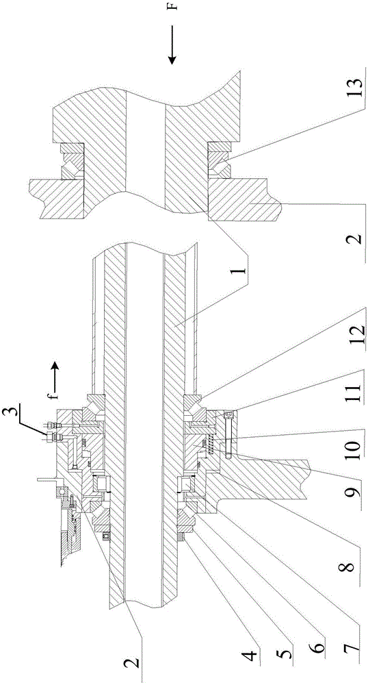
[0024] Please refer to figure 1 , figure 1 It is a schematic structural diagram of the spindle force balance assembly of the friction welding machine provided by the embodiment of the present invention.

[0025] Such as figure 1 As shown in , the front end of the main shaft is fixed as follows: the ...


PUM


Abstract

The invention relates to a spindle force balancing assembly of a friction welding machine. The assembly comprises a spindle and a spindle box and further comprises a balancing device which is assembled on the spindle box and used for exerting axial force on the spindle; and the direction of the force exerted on the spindle by the balancing device is opposite to that of the axial force on the spindle during working. After the balancing device is added, the axial force exerted on the spindle by the balancing device can partially or completely offset the axial force on the spindle during working, so that the axial force on a bearing of the spindle is reduced, and correspondingly, the axial thrust capable of being borne by the friction welding machine is remarkably increased; and meanwhile, the axial force on the spindle is remarkably reduced, and the service life of the bearing of the spindle is correspondingly prolonged. The invention further discloses the friction welding machine provided with the spindle force balancing assembly.

Description

technical field [0001] The invention relates to the technical field of friction welding production, in particular to a friction welding machine and a spindle force balance assembly thereof. Background technique [0002] Friction welding is a solid-state welding method to achieve welding. Under the action of pressure and constant or increasing pressure and torque, the relative motion between the welding contact end faces and the surrounding area is used to generate frictional heat and plastic deformation heat, so that the temperature of the nearby area When the temperature rises to a temperature range close to but generally lower than the melting point, the deformation resistance of the material decreases, the plasticity increases, and the oxide film on the interface is broken. A solid-state welding method that achieves welding by crystallization. [0003] Before welding, among a pair of workpieces to be welded, one is clamped in a rotating fixture, called a rotating workpie...

Claims


Application Information

Patent Timeline
Patent Type & Authority Applications(China)
IPC IPC(8): B23K20/12B23K20/26
CPCB23K20/12B23K20/26
Inventor 徐晓菱杨昭洪王纯远李晓春
Owner CHONGQING TURBO FLOW MACHINERY MFG
Why Eureka
Try Eureka