A multi-channel fiber optic ring acoustic emission detection system and demodulation method

A technology of acoustic emission detection and detection system, which is applied in the direction of using acoustic emission technology for material analysis, processing response signals of detection, etc., can solve the problems of affecting acoustic emission signal detection, phase difference, affecting demodulation, etc., and achieves low hardware cost. , the operation speed is fast, and the response frequency is wide.

Active Publication Date: 2019-03-26
BEIHANG UNIV
View PDF7 Cites 0 Cited by
  • Summary
  • Abstract
  • Description
  • Claims
  • Application Information

AI Technical Summary

Problems solved by technology

The optical fiber phase-locked loop method needs to add PZT phase modulation, which has a certain impact on the frequency response of the sensing system, and the active compensation device is not conducive to the formation of an all-fiber network and the construction of a multi-channel detection system; the differential cross multiplication method and the inverse Both methods require a mixer to mix the external signal and the system interference signal. In this process, the local oscillator frequency and the carrier frequency are not exactly the same, which is easy to cause frequency difference and phase difference, thus affecting the subsequent solution. tone
[0004] The existing optical sensor acoustic emission detection technology is mainly concentrated in the field of fiber Bragg grating acoustic emission detection, such as Chinese patent CN105116056A "acoustic emission positioning system and method based on FBG sensing system and second-order statistics", CN102419348A "a fiber-based Acoustic emission signal power type non-destructive testing method of Bragg grating" and other public acoustic emission detection systems are based on fiber Bragg grating acoustic emission sensors, fiber Bragg gratings are susceptible to external influences such as temperature, thus affecting the detection of acoustic emission signals

Method used


Image

  • A multi-channel fiber optic ring acoustic emission detection system and demodulation method
  • A multi-channel fiber optic ring acoustic emission detection system and demodulation method
  • A multi-channel fiber optic ring acoustic emission detection system and demodulation method

Examples


Embodiment Construction

[0016] The specific implementation manner of the present invention will be described in detail below in conjunction with the accompanying drawings. It should be emphasized that the following description is only exemplary and not intended to limit the scope of the invention and its application.

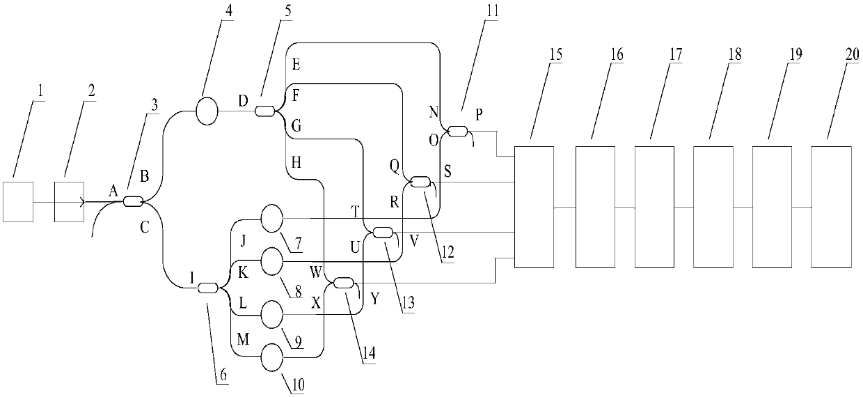
[0017] Such as figure 1As shown, the present invention is a structural schematic diagram of a multi-channel optical fiber ring acoustic emission detection system. The detection system includes: narrowband light source 1, isolator 2, 5 2*2 couplers (3,11-14), 2 1*4 couplers (5,6), reference fiber ring 4, 4 sensing fibers Ring (7-10), photoelectric detection circuit 15, bandpass filter circuit 16, preamplifier circuit 17, analog-to-digital conversion circuit 18, FPGA19, computer 20; Wherein, the A end of the first 2*2 coupler 3 is isolated from The output end of the device 2 is connected, the B end of the first 2*2 coupler 3 is connected with the reference fiber ring 4, and the C end o...


PUM

PropertyMeasurementUnit
wavelengthaaaaaaaaaa
poweraaaaaaaaaa

Abstract

The invention provides a multichannel optical fibre ring sound emission detection system and a demodulation method, and aims to detect a plurality of sound emission signals in a structure body quickly and accurately and monitor the health conditions of the structure body in real time. The sound emission detection system comprises a narrow-band light source, an isolator, a coupler, a reference optical fibre ring, a sensing optical fibre ring, a photo-electronic detection circuit, a band pass filtering circuit, a preamplifier circuit, an analogue-to-digital conversion circuit, an FPGA and a computer. The multichannel optical fibre ring sound emission detection system and the demodulation method are mainly used in the field of sound emission detection; compared with a conventional piezoelectric sensor, the multichannel optical fibre ring sound emission detection system have the advantages of anti-electromagnetic interference and high sensitivity; compared with a conventional demodulation method, the demodulation method has the advantages of simplicity, high efficiency, high calculation speed and low cost, and is beneficial to practical engineering application.

Description

technical field [0001] The invention belongs to the technical field of acoustic emission detection, and in particular relates to a multi-channel optical fiber ring acoustic emission detection system and a demodulation method. Background technique [0002] Acoustic emission technology originated in the 1950s. The generation of acoustic emission signals directly comes from dynamic information such as crack defects and expansion inside components or materials. The characteristics of acoustic emission detection technology make it especially suitable for dynamic safety detection, health monitoring, integrity assessment, early damage warning and failure prevention of mechanical equipment structures, etc. Therefore, acoustic emission technology has always attracted attention. It is widely used in machinery manufacturing, petrochemical and other fields. [0003] At present, the acoustic emission detection technology is mainly based on piezoelectric ceramic sensors. This method has ...

Claims


Application Information

Patent Timeline
Patent Type & Authority Patents(China)
IPC IPC(8): G01N29/14G01N29/44
CPCG01N29/14G01N29/44
Inventor 魏鹏夏东李成贵
Owner BEIHANG UNIV
Why Eureka
Try Eureka