Rotor of permanent magnet synchronous motor and motor

A technology for permanent magnet synchronous motors and rotors, which is applied in the direction of synchronous machine parts, magnetic circuit rotating parts, magnetic circuits, etc., to achieve the effects of reducing eddy current loss, reducing electromagnetic noise, and high sine of air gap flux density

Active Publication Date: 2017-01-18
GREE ELECTRIC APPLIANCES INC
View PDF6 Cites 15 Cited by
  • Summary
  • Abstract
  • Description
  • Claims
  • Application Information

AI Technical Summary

Problems solved by technology

[0003] An object of the present invention is to propose a rotor for a permanent magnet synchronous motor that solves the pr...

Method used


Image

  • Rotor of permanent magnet synchronous motor and motor
  • Rotor of permanent magnet synchronous motor and motor
  • Rotor of permanent magnet synchronous motor and motor

Examples


Embodiment 1

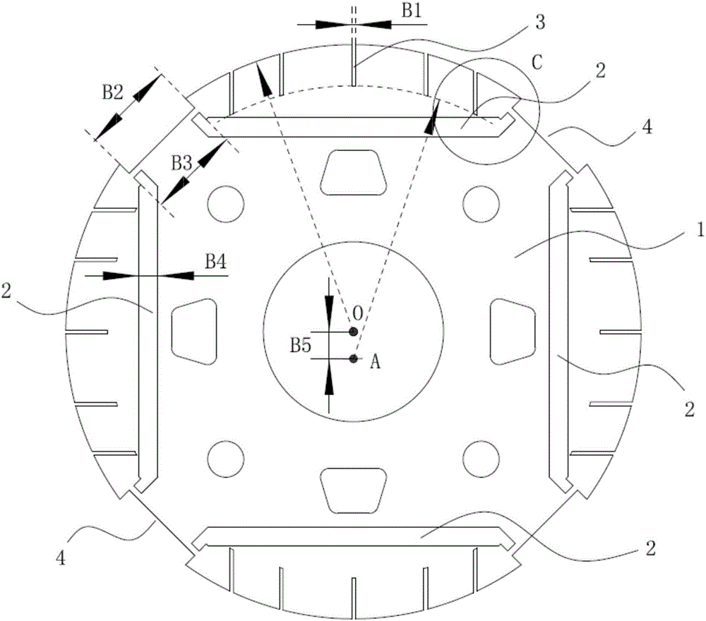
[0028] The preferred embodiment discloses a rotor of a permanent magnet synchronous motor. Such as figure 1 with figure 2 As shown, a plurality of magnetic steel slots 2 are evenly distributed along the circumferential direction on the rotor body 1, and permanent magnets (not shown in the figure) are inserted in the magnetic steel slots 2, and the polarities of adjacent permanent magnets are opposite; A plurality of slits 3 are arranged on the outer edge of the magnetic steel slot 2 corresponding to the position, the slits 3 are connected to the air gap between the stator and the rotor, and the inner ends of the slits 3 are located on the same arc line.

[0029] Preferably, the width of all slits 3 is the same; the slits 3 corresponding to the same magnetic steel groove 2 are the same group, and all the slits 3 in each group of slits 3 are arranged symmetrically about the center line of the permanent magnet; each group of slits The slits 3 include five slits 3, and the roto...

Embodiment 2

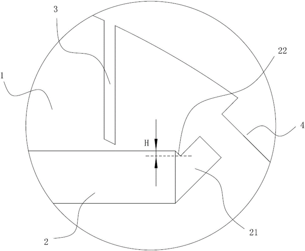
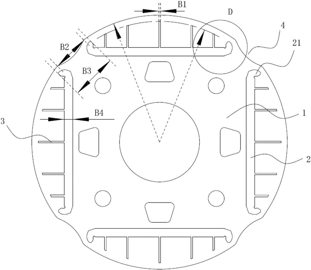
[0039] This preferred embodiment discloses a rotor of a permanent magnet synchronous motor, the structure of which is basically the same as that of the first preferred embodiment. The difference is that if image 3 with Figure 4 As shown, a plurality of slits 3 are provided on the outer edge of the rotor body 1 corresponding to the magnetic steel groove 2, the slits 3 communicate with the magnetic steel groove 2, and the outer ends of the slits 3 are located on the same arc line superior. The center of the arc line where the outer end of the slit 3 is located coincides with the center of the rotor body 1 .

[0040] The magnetic circuit of the rotor is improved, the air gap magnetic field distribution is more sinusoidal, the influence of high harmonics on the stator, rotor and permanent magnet is weakened, the electromagnetic noise is further suppressed, and the core loss is reduced.

Embodiment 3

[0042] This preferred embodiment discloses a rotor of a permanent magnet synchronous motor, the structure of which is basically the same as that of the second preferred embodiment. The difference is that if Figure 5 As shown, in a group of slits 3 corresponding to the same magnetic steel slot 2, all the slits 3 are inclined to the left and right sides with the center line of the magnetic steel slot 2 as the reference, and at the center line of the corresponding magnetic steel slot 2 A through hole 5 is provided, and the through hole 5 communicates with the magnetic steel slot 2 .

[0043] In order to improve the air gap flux density and rotor flux, and increase the anti-demagnetization ability of the permanent magnet, the angle θ between the slit 3 and the outer surface of the magnetic steel slot 2 is preferably greater than or equal to 30° and less than or equal to 60°.

[0044] In order to ensure that the permanent magnet is not easy to break when it is stressed, suppress ...


PUM


Abstract

The invention discloses a rotor of a permanent magnet synchronous motor (PMSM) and a motor, belongs to the technical field of motors and solves the problem that a conventional device has a lot of higher harmonic magnetic fields. The rotor of the PMSM has a plurality of magnetic steel grooves uniformly distributed in the circumferential direction of a rotor body, permanent magnets are inserted in the magnetic steel grooves, and the adjacent permanent magnets are opposite in polarity. A plurality of slits are arranged in the outer edge of the rotor body at positions corresponding to the magnetic steel grooves, the slits communicate with an air gap between a stator and the rotor, and the inner ends of the slits are on the same arc line; or, a plurality of slits are arranged in the outer edge of the rotor body at the positions corresponding to the magnet steel grooves, the slits communicate with the magnet steel grooves, and the outer ends of the slits are located on the same arc line. The rotor of the PMSM and the motor solve the problem that lots of harmonics exist in the air gap between the inner side wall of the stator and the outer side wall of the rotor, reduce the electromagnetic noise of the motor and ensure air-gap flux density and sinusoidal features.

Description

technical field [0001] The invention relates to the technical field of motors, in particular to a rotor of a permanent magnet synchronous motor and a motor including the rotor. Background technique [0002] In the existing permanent magnet synchronous motor, there are a large number of high-order harmonic magnetic fields in the air gap between the inner wall of the stator and the outer wall of the rotor, thereby generating electromagnetic excitation forces of various orders, making the stator, rotor and permanent magnets Generate vibration and form serious electromagnetic noise; the high-order harmonic magnetic field circulating in the stator and rotor will also increase the eddy current loss, which will easily cause the permanent magnet to heat up and reduce the anti-demagnetization ability of the permanent magnet. Contents of the invention [0003] An object of the present invention is to propose a rotor for a permanent magnet synchronous machine which solves the problem...

Claims


Application Information

Patent Timeline
IPC IPC(8): H02K1/27H02K5/24H02K21/02H02K11/01
CPCH02K1/276H02K5/24H02K21/02
Inventor 张辉王晶
Owner GREE ELECTRIC APPLIANCES INC
Why Eureka
Try Eureka