

Laser gyroscope resonator loss measuring device and method
A technology of laser gyro and measuring device, which is applied in measuring device, gyro effect for speed measurement, gyro/steering sensing device, etc., can solve the problems of no reports or literatures, no literatures found, etc., and achieves compact structure and simplified light source. Design and easy operation
Inactive Publication Date: 2011-09-28
XIAN TECHNOLOGICAL UNIV
View PDF0 Cites 10 Cited by
- Summary
- Abstract
- Description
- Claims
- Application Information
AI Technical Summary
Problems solved by technology
The project team of this invention has searched domestic and foreign patent documents and published journal papers, and has not found any documents closely related to the present invention, nor has it found any reports or documents similar to the present invention
Method used
View moreImage
Smart ImageViewing Examples

Examples
Embodiment 1
Embodiment 2
Embodiment 3
Login to View More PUM
 Abstract
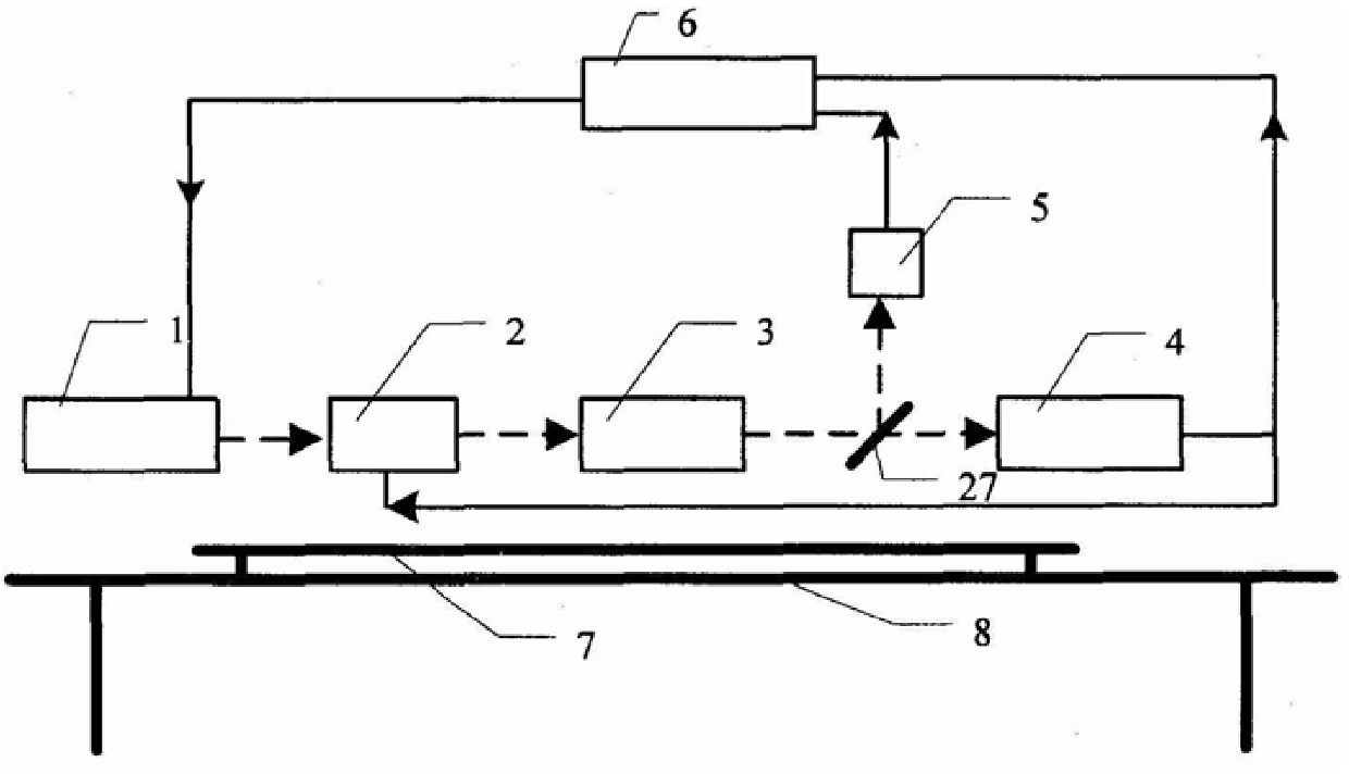
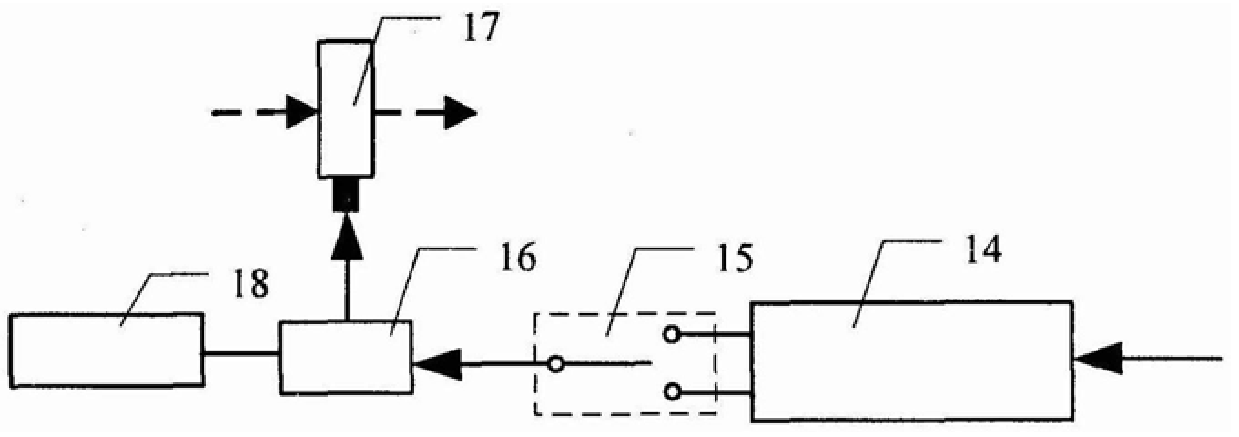
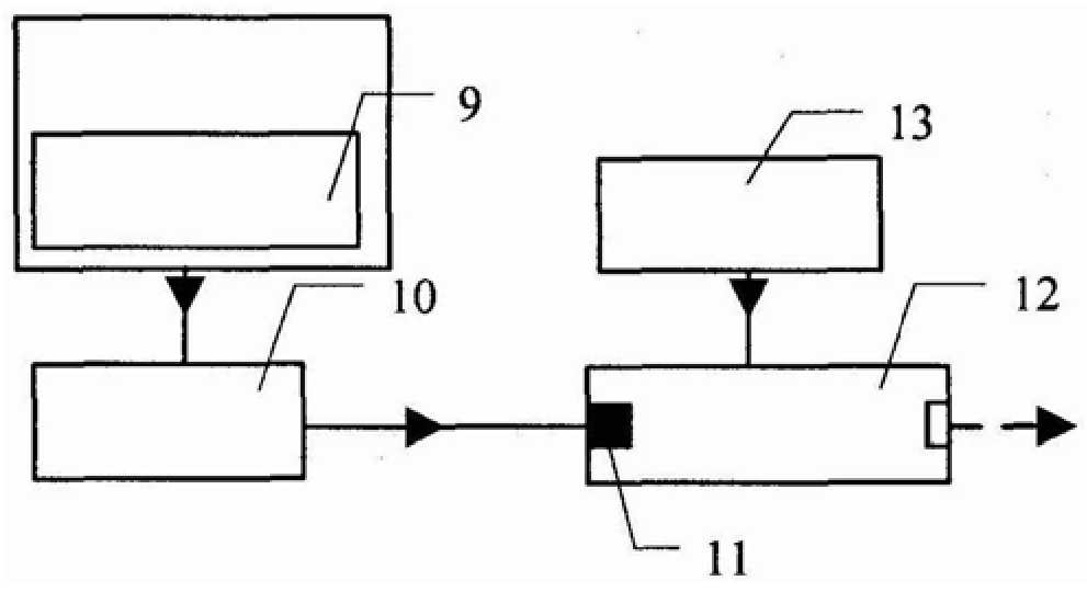
The present invention first provides a device and method capable of accurately measuring the loss of the laser gyroscope optical resonant cavity in real time. The main components of the basic equipment are sequentially installed with a laser light source assembly, an acousto-optic modulator, and an optical path adjustment assembly according to the direction of light propagation. etc. After the optical path passes through the half-mirror installed in the optical path adjustment component, the laser gyro resonator loss measurement and the real-time imaging of the diaphragm and light spot in the resonant cavity are respectively completed through the photoelectric detection component and the CCD component. The present invention also solves the problem of low accuracy of measuring the loss of the unknown laser gyro resonator by a single method. When the loss of the laser gyro resonator is high, the resonance path is selected for measurement, and when the loss is low, the time attenuation path is selected for measurement by switching the switch. After the device is completed, the relative position of the diaphragm and the laser spot in the resonant cavity can also be measured in real time. High measurement accuracy and low measurement cost. The signal-to-noise ratio of the measuring device is high, the device is easy to debug, compact in structure and small in size.
Description
Laser gyroscope resonator loss measuring device and method technical field The invention belongs to the technical field of laser gyroscope testing, and mainly relates to the loss measurement of the laser gyroscope resonator cavity, the real-time imaging of the aperture in the resonator cavity and the laser spot, and the measurement of the loss of different laser gyroscope resonator cavities by different methods, specifically A laser gyro cavity loss measuring device and method. Background technique Laser gyroscope is an optical gyroscope based on Sagnac effect. The basic principle of the laser gyro is: when the laser rotates with the carrier, the two beams of light output by the laser generate an optical path difference when they run in reverse in the ring optical path, so that the resonant frequencies of the two laser beams are different, and the frequency difference at the output ends varies with the angle. Proportional change, so the speed can be obtained by measuring ...
Claims
Login to View More Application Information
Patent Timeline
 IPC IPC(8): G01C19/00G01C19/58
Inventor刘卫国高爱华徐昌杰吴威陈志超牛同壮
OwnerXIAN TECHNOLOGICAL UNIV