Connecting node of assembled whole thick prefabricated slab unit and slab unit thereof

A connection node, prefabricated technology, applied in the direction of floors, building components, buildings, etc., can solve the problems of difficulty, failure, and few applications, and achieve the effect of enhancing strength and preventing relative movement.

Inactive Publication Date: 2017-01-25
刘祥锦
View PDF9 Cites 15 Cited by
  • Summary
  • Abstract
  • Description
  • Claims
  • Application Information

AI Technical Summary

Problems solved by technology

In this form, the compressive stress of the friction force comes from the post-tensioned prestressed steel strands on site. Because of the special requirements of the connection, the construction process of the prestressed steel strands is cumbersome and difficult. The technical requirements are very high; in addition, the prestressing purpose of the joint tension is for the connection, and additional stress is generated on the original assembled components, which not only increases the design difficulty but also affects the project cost; and when using the "IMS" system , prestressed friction joints not only need to meet the relevant regulations of reinforced concrete structures, but also meet the requirements of "Technical Regulations for Integral Prestressed Prefabricated Slab-Column Structures CECS52: 2010", which is only an association standard regulation, not a national standard. From On the other hand, it indirectly shows that there are some problems in the connection method of the "IMS" system, or at least it shows that it is not a perfect structural form, and it is an implementation technology that has not passed national approval; in application, it is difficult to construct on site—that is, it is not suitable for industrial construction and the cost is high. , The implementation of standards was hindered, resulting in not many applications in the past 20 or 30 years

Method used


Image

  • Connecting node of assembled whole thick prefabricated slab unit and slab unit thereof
  • Connecting node of assembled whole thick prefabricated slab unit and slab unit thereof
  • Connecting node of assembled whole thick prefabricated slab unit and slab unit thereof

Examples


Embodiment 1

[0102] Example 1 - Prefabricated densely ribbed composite panel unit

[0103] Preferably: the prefabricated ribbed composite floor unit has four connection surfaces. In order to better illustrate the connection surfaces, the form of the connection surfaces depends on the connection objects and requirements, and the four connection surfaces are different.

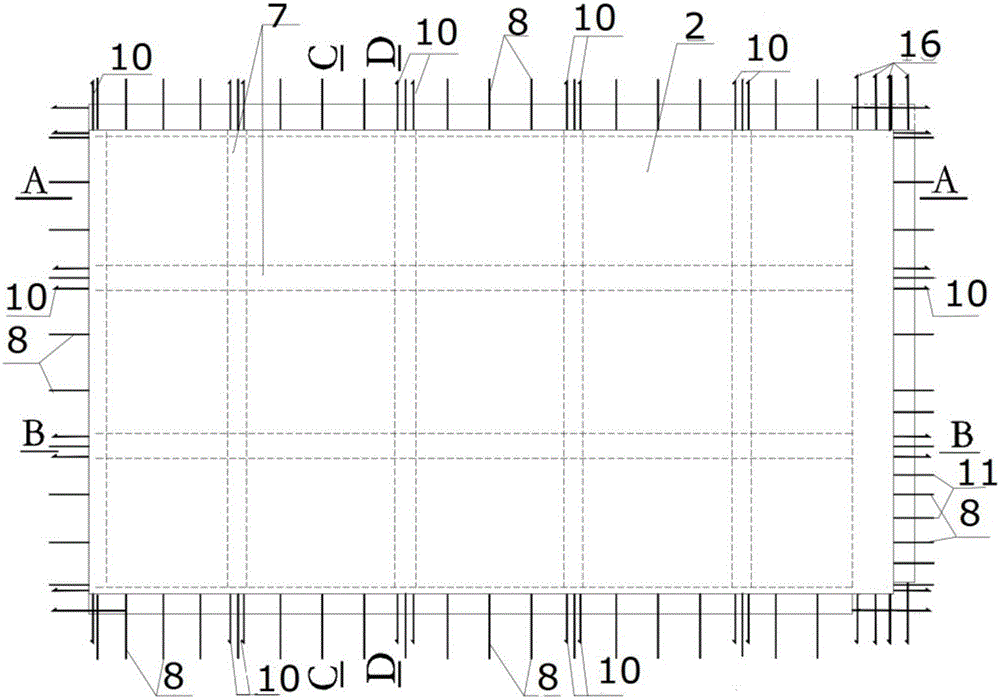
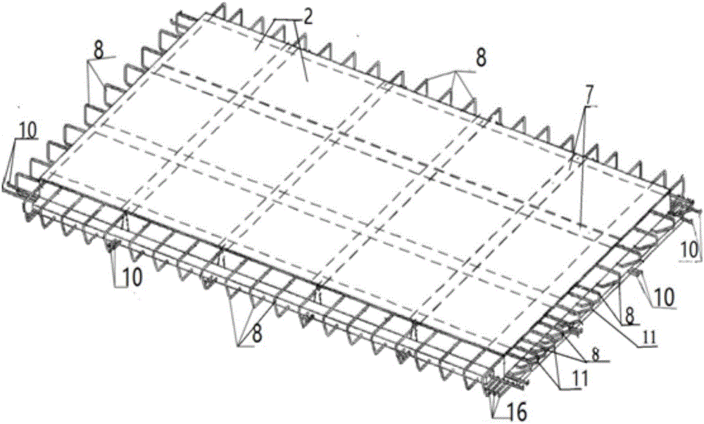
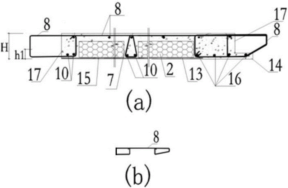
[0104] Figure 1-6 It is a structure of prefabricated dense-ribbed composite panel unit of the present invention.

[0105] like Figure 1-6 shown in figure 1 The direction and orientation of the prefabricated densely ribbed composite slab unit is a flat cuboid prefabricated component with upper and lower surface surfaces and four connecting surfaces, and there are several ribbed prefabricated floor slab ribs arranged vertically and horizontally inside. 7. There are two ribbed lower steel bars protruding from the connecting surface at each slab rib, and a linear prefabricated prefabricated floor slab reinforcement 10 with ...

Embodiment 2

[0109] Example 2 - Prefabricated Solid Panel Units

[0110] Figure 7-10 It is a prefabricated solid panel unit structure of the present invention.

[0111] like Figure 7-10 As shown, the prefabricated solid slab unit is a flat cuboid prefabricated component with upper and lower surfaces and four connecting surfaces, each side has an edge member, and the bottom reinforcement of the component is equipped with prefabricated floor lower reinforcement 10, and its four connecting surfaces All are rough surfaces, and the area of ​​the rough surface is not less than 80% of the joint surface.

[0112]The four connecting surfaces of the prefabricated solid slab unit are reserved with connecting steel bars and the lower part of the prefabricated floor slab 10; The upper transverse section and the lower transverse section of the closed connecting steel bar are parallel to the plate surface, and the exposed section protruding from the vertical connecting surface 17 is shorter. form a...

Embodiment 3

[0117] Example 3 - Connection nodes of prefabricated full-thickness prefabricated floor slabs

[0118] Figure 11-30 It shows the connection nodes of the prefabricated full-thickness prefabricated floor slab of the present invention.

[0119] Figure 11 It is a schematic diagram of the assembly of the full-thickness prefabricated floor slab, including four prefabricated floor slabs with ribbed composite panels b 1 , b 2 , b 3 , b 4 , the vertical component column 1 and the load-bearing wall 6, the horizontal component beam 3; specifically, unit b 1 with b 2 are spliced ​​together, and the connection nodes are 2C and 2D, forming a whole prefabricated floor, b 1 and b 2 with b 4 The joints 2A and 2B connected to form a wide flat beam are supported on the column 1, b 1 and b 2 The nodes connected to the load-bearing wall 6 are 1A and 1B, and the connection is also applicable to the beam, b 2 with b 3 At the same time, the joints 1C and 1D connected by the beam 3 are ...


PUM


Abstract

The invention discloses a connecting node of an assembled whole thick prefabricated slab. Connecting steel bars are reserved on the connecting surface of a prefabricated slab unit in the mode, the exposed parts of the connecting steel bars are ' '-shaped, and the exposed parts and the connecting surface form a closed polygon. In the connecting mode for the prefabricated slab unit and a beam or a wall, the connecting steel bars of the prefabricated slab unit are inserted with steel bars configured for the beam or the wall together at the connecting positions in a penetrating mode. Viewing from the cross section of the whole connecting node, the connecting steel bars and the steel bars configured for the beam or the wall form a single closed stirrup or a composite stirrup, and longitudinal bolt steel bars penetrate into the inner corner position of the single closed stirrup or the composite stirrup. The connecting node of the whole thick prefabricated slab unit can achieve the equivalent performance as a prefabricated slab connecting nodes and a cast-in-place concrete structure while achieving higher prefabrication rate and assembly rate. The invention further provides the whole thick prefabricated slab unit for achieving the connecting mode.

Description

technical field [0001] The invention relates to a prefabricated assembled concrete structure, in particular to a connection node of an assembled prefabricated floor slab and a floor slab unit thereof. Background technique [0002] Since prefabricated buildings conform to the production mode of environmental protection and energy saving, the country has proposed the development goal of making prefabricated buildings account for 30% of new buildings in about 10 years. The specific notice of the special 2016 annual project declaration guide mentioned the research content of the project (excerpted relevant content): research on the new connection nodes of prefabricated concrete structures and their basic structural performance, research on the industrialization adaptability of concrete prefabricated structural systems in the 8-degree area, and put forward The new series of connection node forms meet the same performance requirements as cast-in-place structures. [0003] Assembl...

Claims


Application Information

Patent Timeline
Patent Type & Authority Applications(China)
IPC IPC(8): E04B5/02E04B1/41
CPCE04B1/41E04B5/023
Inventor 刘祥锦
Owner 刘祥锦
Why Eureka
Try Eureka