Reinforced structure for coupling beam of reinforced concrete

A reinforced concrete and reinforced structure technology, which is applied in building construction, building maintenance, construction, etc., can solve the problems that the coupling beam cannot meet the seismic design requirements, the rigidity of the lateral force resistance system increases greatly, and the ductility and deformation capacity are ignored. The effects of shortening the reinforcement construction period, improving engineering efficiency, and simplifying the construction process

Inactive Publication Date: 2017-01-25
BEIJING UNIVERSITY OF CIVIL ENGINEERING AND ARCHITECTURE
View PDF3 Cites 2 Cited by
  • Summary
  • Abstract
  • Description
  • Claims
  • Application Information

AI Technical Summary

Problems solved by technology

On the one hand, it is used to solve the problem that in the existing coupling beam reinforcement technology, due to the increase in the stiffness of the coupling beam, the stiffness of the lateral force system is greatly increased, and the ductility and deformation capacity are ignored, so that the reinforced coupling beam cannot meet the seismic design requirements.
On the other hand, it solves the problem that in the existing coupling beam reinforcement technology, the beam needs to be treated more strictly and the on-site construction process is more complicated.

Method used


Image

  • Reinforced structure for coupling beam of reinforced concrete
  • Reinforced structure for coupling beam of reinforced concrete
  • Reinforced structure for coupling beam of reinforced concrete

Examples


Embodiment 1

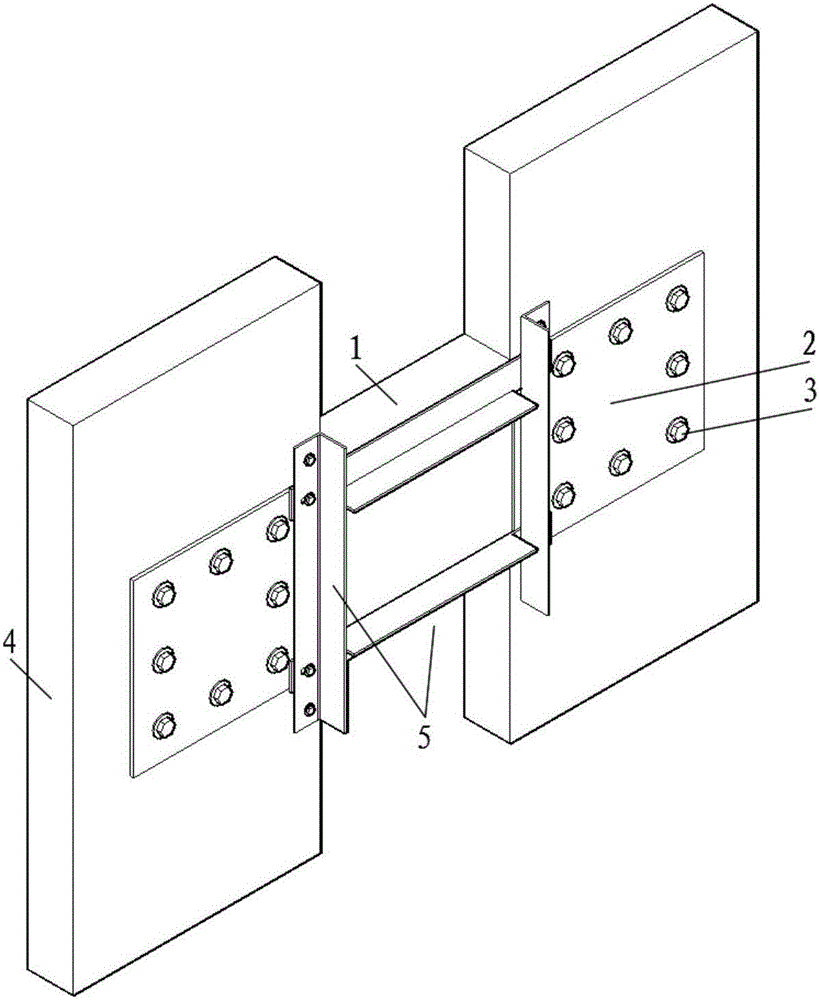
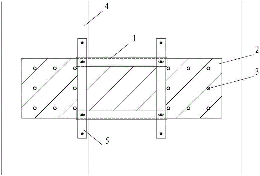
[0032] Such as figure 1 , figure 2 As shown, a reinforced concrete coupling beam reinforcement structure includes a coupling beam 1, a steel plate 2, a shear wall 4 at both ends of the coupling beam, and a buckling restraint frame 5. The steel plate 2 is connected to the shear walls 4 at both ends of the connecting beam through chemical anchor bolts, and the gap between the screw rod of the chemical anchor bolt and the wall of the bolt hole is filled with chemical adhesive. The vertical frames on both sides of the buckling restraint frame 5 are respectively connected to the steel plates 2 on the shear wall 4 through bolts, and the vertical frames extend from the upper and lower ends of the steel plate 2 to connect with the corresponding shear wall 4 connection, the joint between the vertical frame of the buckling constrained frame 5 and the steel plate 2 is provided with a horizontally arranged oblong hole, the joint between the transverse frame of the buckling constrained f...

Embodiment 2

[0047] This embodiment is basically the same as Embodiment 1. For the sake of brevity, in the description process of this embodiment, the same technical features as Embodiment 1 will not be described, and only the differences between this embodiment and Embodiment 1 will be described: , the vertical frame and the horizontal frame are welded to form the buckling restraint frame (5), and the thickness of the contact part of the steel plate (2) with the shear wall (4) is greater than that of the contact part with the coupling beam (1) thickness.

[0048]Specifically: the thickness of the contact part between the steel plate 2 and the shear wall 4 at both ends of the connecting beam is 9 mm, and the thickness of the contact part between the steel plate 2 and the connecting beam 1 is 4.5 mm.

[0049] In this embodiment, in order to meet different needs for strengthening the connecting beam, by increasing the thickness of each part of the steel plate, the strength of the connecting ...


PUM

PropertyMeasurementUnit
Thicknessaaaaaaaaaa
Thicknessaaaaaaaaaa
Thicknessaaaaaaaaaa

Abstract

The invention discloses a reinforced structure for a coupling beam of reinforced concrete, comprising a coupling beam, a steel plate and shear walls at the two ends of the coupling beam, wherein the steel plate is set along the vertical side of the coupling beam and connected with the shear walls by a first fastening connection piece; the reinforced structure further comprises a buckling constraint frame; the vertical side frames a the two sides of the buckling constraint frame are respectively connected with the steel plate located o the shear walls at the two sides of the coupling beam by a second fixing connection piece. The vertical side frame extends the upper and lower ends of the steel plate and connected with the corresponding shear wall by the second fastening connection piece; and the intersection of the buckling constraint frame and the steel plate is levelly provided with circular holes. The steel plate and buckling constraint frame in the invention are designed and processed ahead of time with high prefabricating degree, and the field majors in assembly. The buckling constraint frame is adopted, so that the steel plate can develop the strength effectively and improve the shock resistance of the coupling beam. When bending the constraint steel plate, the rigidity of the increased coupling beam is avoided by setting level long circular hole, and the reinforced structure is beneficial for earthquake resistant design requirement.

Description

technical field [0001] The invention relates to the technical field of structural engineering, in particular to a reinforced concrete coupling beam reinforcement structure. Background technique [0002] Shear wall structure, frame-shear wall structure and frame core tube structure are lateral force resistance systems widely used in high-rise buildings, and coupling beams are an important part of these structural lateral force resistance systems. The research shows that the connecting beam connecting two shear walls has an important influence on the seismic performance of the entire lateral force-resisting system. The rationally designed reinforced concrete shear wall structure system, under the action of earthquake, the reinforced concrete coupling beam first yields, and then dissipates the energy input by the earthquake under the action of reciprocating load. Therefore, the coupling beam needs to have sufficient strength, ductility and energy dissipation capacity. [0003...

Claims


Application Information

Patent Timeline
IPC IPC(8): E04G23/02
CPCE04G23/0218
Inventor 程蓓苏启亮杨参天官俊良周梦杰石彩华
Owner BEIJING UNIVERSITY OF CIVIL ENGINEERING AND ARCHITECTURE
Why Eureka
Try Eureka