Compensator, in particular for motor vehicle applications

A compensator and motor vehicle technology, applied in the field of compensators, to achieve the effects of high temperature resistance, high elastic modulus, and small fluidity

A compensator and motor vehicle technology, applied in the field of compensators, to achieve the effects of high temperature resistance, high elastic modulus, and small fluidity

CN106352189AInactive Publication Date: 2017-01-25MAN NUTZFAHRZEUGE AG

Image

  • Compensator, in particular for motor vehicle applications
  • Compensator, in particular for motor vehicle applications
  • Compensator, in particular for motor vehicle applications

Examples


Embodiment Construction

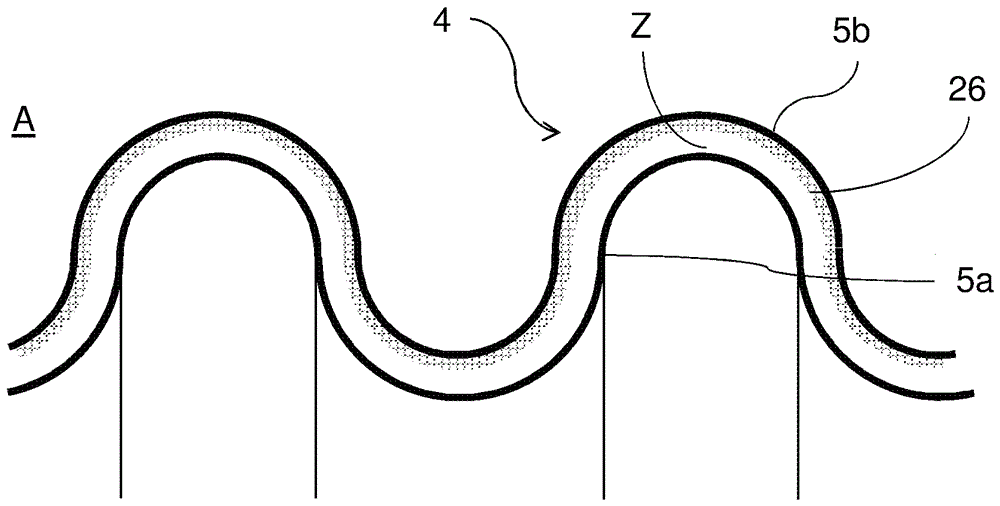
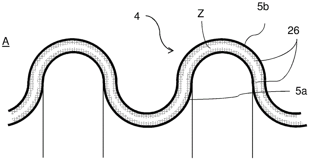
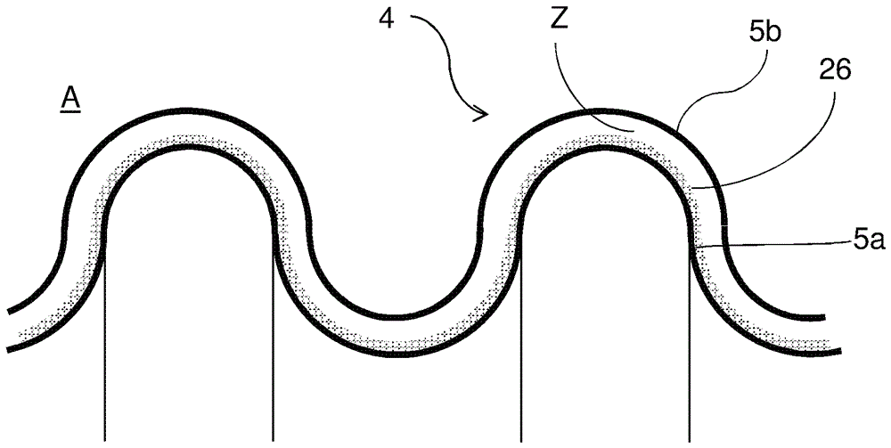
[0038] exist figure 1 shows a schematic cross-sectional view of a compensator 1 which can be used, for example, as an exhaust gas compensator in an exhaust gas recirculation line. The compensator 1 comprises a corrugated or annular corrugated metal bellows 4 . Furthermore, the compensator comprises two conduit connections 2 and 3 for forming a flange connection via which the compensator 1 is installed in a line, for example an exhaust gas recirculation line (not shown).

[0039] In the embodiment shown, the bellows 4 comprises an inner metal layer 5 a and an outer metal layer 5 b , which together form the corrugated wall of the metal bellows 4 . A gap Z is formed between the inner metal layer 5 a and the outer metal layer 5 b into which a friction reducer of a friction-reducing solid is introduced in the form of a continuous intermediate layer 6 extends over the entire length of and adjoins line connections 2 and 3.

[0040] A step in the manufacture of a compensator usuall...


PUM


Abstract

The invention relates to a compensator (1) used for compensating two pipeline elements, in particular for motor vehicle applications. The compensator (1) comprises a multi-layer corrugated pipe (4), which is used as a wall, and comprises at least two stacked layers (5a,5b). A gap (Z) is correspondingly formed between the layers. In order to prevent forming of cracks, friction reduction agent (6) exists in the at least one gap (Z).

Description

technical field [0001] The invention relates to a compensator for compensating relative movements of two line elements, in particular as flexible line elements for motor vehicle applications, comprising a multilayer bellows comprising as a wall At least two layers placed one above the other, correspondingly forming interspaces between the layers. Background technique [0002] Especially in motor vehicles with internal combustion engines, but also in the case of conventional internal combustion engines (stationary and moving turbine engines), as well as in industrial plants and chemical reactors, vibrations and relative movements occur during operation, which also Passable to catheter. This is induced, for example, by oscillating masses, imbalances of rotating components and by moments of inertia when the engine load changes. In order to compensate movements in the conduit, in particular due to the aforementioned vibrations or relative movements, in the case of thermodynami...

Claims


Application Information

Patent Timeline
25 Jan 2017
Publication
CN106352189A
IPC
F16L51/02
CPC
F16L51/022; F16L51/025; F01N13/1816; F16J3/043; F16L11/15; F16L27/1004; F16L27/11; F16L51/035
Inventors
W.希巴尔斯基; S.布赫尔