Full-automatic closed-loop testing system for fault indicator

A fault indicator, fully automatic testing technology, applied in the direction of instruments, measuring devices, measuring electrical variables, etc., can solve rough simulation of short circuit/ground fault, not suitable for batch fault indicator inspection, the console and the master station system are not integrated Together and other problems, to achieve the effect of simplifying the inspection method, high level of automation, and good flexibility

Pending Publication Date: 2017-01-25
SHANGHAI JIAQI NETWORK TECH CO LTD
View PDF4 Cites 1 Cited by
  • Summary
  • Abstract
  • Description
  • Claims
  • Application Information

AI Technical Summary

Problems solved by technology

[0006] (1) Inspection scheme 1) can only roughly simulate short-circuit / ground faults, and is not suitable for inspection of batch fault indicators
[0007] (2) Compared with the inspection scheme 1), the inspection scheme 2) has been greatly improved, but the console and the main station system are not integrated together. The pass / failure of the fault indicator inspection needs manual judgment, and the automatic inspection cannot be realized. Require

Method used


Image

  • Full-automatic closed-loop testing system for fault indicator

Examples


Embodiment

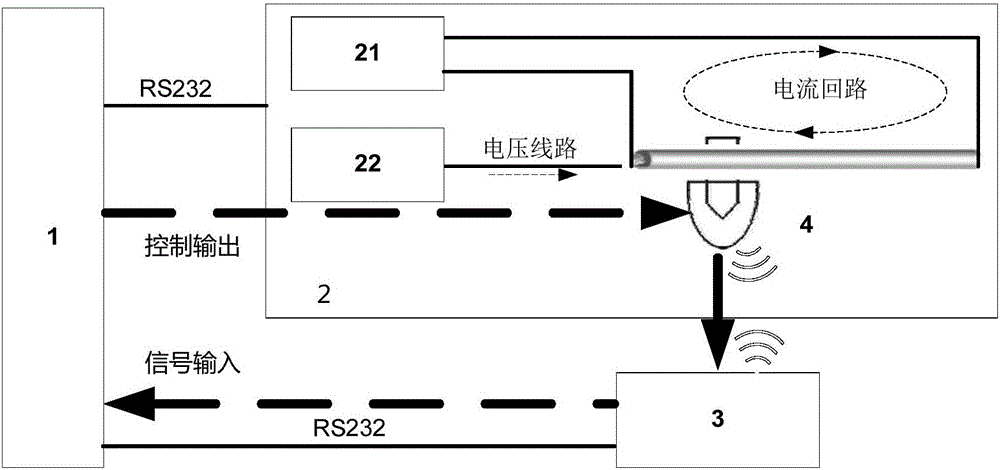
[0028] Such as figure 1 As shown, a closed-loop full-automatic testing system for a fault indicator includes a console 1 embedded with an analog master station, a testing unit 2 and a monitoring unit 3, and the console 1, testing unit 2, and monitoring unit 3 and the console 1 are connected in turn to form a closed loop, and the test unit 2 includes a voltage source 22 and a current source 21 connected to the console 1 respectively, and the voltage source 22 and the current source 21 are respectively connected to the fault indicator to be tested 4, the fault indicator 4 to be tested is connected to the monitoring unit 3, and the console 1 is connected to the fault indicator 4 to be tested.

[0029] The console 1 is connected to the voltage source 22, the current source 21 and the fault indicator 4 to be tested respectively through the RS232 bus. The fault indicator 4 to be tested is connected with the monitoring unit 3 through a wireless transmission network. The wireless tr...


PUM


Abstract

The invention relates to a full-automatic closed-loop testing system for a fault indicator. The full-automatic closed-loop testing system comprises a console with an embedded simulator station, a testing unit and a monitoring unit, wherein the console, the testing unit and the monitoring unit are sequentially connected to form a closed loop, the testing unit comprises a voltage source and a current source which are respectively connected with the console and the fault indicator to be tested, the fault indicator to be tested is connected with the monitoring unit, and the console is connected with the fault indicator to be tested. Compared with the prior art, the full-automatic closed-loop testing system has the advantages of high automation level, good flexibility, high testing efficiency and the like.

Description

technical field [0001] The invention relates to a fault indicator testing device, in particular to a closed-loop full-automatic testing system for the fault indicator. Background technique [0002] The current inspection methods for distribution line fault indicators generally include: [0003] 1) Separate current source and voltage source. The separate current source and voltage source are used to meet the conditions of short circuit fault / ground fault, and the indicating unit forms a local alarm indication or sends alarm information to the monitoring unit, and the monitoring unit then sends the alarm information to the master station system and displays it. The advantage of this approach is that it is simple and easy to implement. All existing resources are used to build a test environment, which is applicable to the initial R&D stage. [0004] 2) The test device is formed by integrating the current source and the voltage source, but the console is separated from the ana...

Claims


Application Information

Patent Timeline
Patent Type & Authority Applications(China)
IPC IPC(8): G01R35/00
Inventor 彭巍
Owner SHANGHAI JIAQI NETWORK TECH CO LTD
Why Eureka
Try Eureka