Method for determining leakage risk monitoring point of CO2 burial

A risk monitoring, CO2 technology, applied in design optimization/simulation, special data processing applications, instruments, etc., can solve the problems of repeated monitoring point layout, human production, life, ecosystem damage, plant and animal fatal injury, etc.

Active Publication Date: 2017-01-25
CHINA PETROLEUM & CHEM CORP +1
View PDF5 Cites 11 Cited by
  • Summary
  • Abstract
  • Description
  • Claims
  • Application Information

AI Technical Summary

Problems solved by technology

In addition, if the concentration of carbon dioxide in the shallow underground layer rises, it will not only cause fatal damage to plants and animals, but also pollute groundwater, causing huge damage to human production, life, and ecosystems
Therefore, how to effectivel

Method used


Image

  • Method for determining leakage risk monitoring point of CO2 burial
  • Method for determining leakage risk monitoring point of CO2 burial
  • Method for determining leakage risk monitoring point of CO2 burial

Examples


Embodiment Construction

[0066] In order to clearly illustrate the technical features of the solution, the solution will be described below through specific implementations.

[0067] This example is a method to determine CO 2 The method for burying leak risk monitoring points includes the following steps:

[0068] Step 1: Establish a fine geological model of the target reservoir based on the logging data and the previous understanding of the distribution of sublayers and the physical properties of the reservoir, and describe in detail the porosity, permeability, heterogeneity of high permeability channels and Fault distribution and permeability, open state;

[0069] Step 2: Use the reservoir numerical simulation method to match the production history and formation pressure of the target oil reservoir, and obtain the current fluid field, pressure field and stress field of the target oil reservoir;

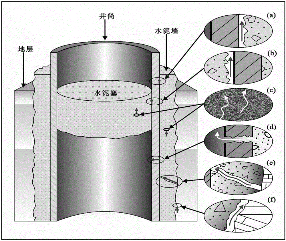
[0070] Step 3: Considering the cementing quality, downhole corrosion, etc., establish the wellbore int...


PUM


Abstract

The invention discloses a method for determining a leakage risk monitoring point of CO2 geological burial, comprising the following steps: designing a way of based on an established fine geological model, adopting an oil reservoir numerical simulation method to obtain the current fluid field, pressure field and ground stress field of a target oil reservoir by means of history fitting, establishing a fault leakage model, a wellbore leakage model, a cap rock leakage model in sequence, based on reservoir parameter obtained by numerical value simulation fitting, performing a CO2leakage risk analysis in combination with the respective established leakage models to determine a risk region where CO 2leakage may occur, a leakage means and an estimated leakage amount, and making a CO2 leakage monitoring plan on this basis. As known from the description on the above scheme, the method disclosed by the invention has the beneficial effects of effectively preventing and monitoring CO2 leakage, ensuring effectiveness, safety and durability of CO2 geological storage, and avoiding repeated arrangement of monitoring points and waste of monitoring costs.

Description

technical field [0001] The invention relates to the field of environmental monitoring, in particular to a method for determining CO 2 Methods for monitoring sites of leakage risk in geological storage. Background technique [0002] Environmental problems caused by global climate change have brought unprecedented challenges to human beings. Among the causes of climate change, CO, a greenhouse gas, 2 emission problems are becoming more and more prominent, so the CO 2 Disposal technologies for emissions into the atmosphere are attracting increasing attention. CO 2 Capture and storage (CCS) as an emerging CO with potential for large-scale applications 2 Disposal technologies for CO used in fossil fuels 2 Near-zero emissions offer a possibility. At the same time, CO 2 Oil flooding is one of the frontier development directions of tertiary oil recovery technology, and it is also one of the most valuable CO 2 field of application. With the continuous development of explorat...

Claims


Application Information

Patent Timeline
IPC IPC(8): G06F17/50
CPCG06F30/20
Inventor 王晓慧郭爱洪陈健飞吕德东刘璐席琦
Owner CHINA PETROLEUM & CHEM CORP
Why Eureka
Try Eureka